D. user interface display – HTP EL-399NVWH User Manual
Page 64
64
LP- 346 REV. 3.20.14
2. Note the fault message displayed and refer to Part D in this section for an explanation of the message along with several suggestions
for corrective actions.
3. Press the reset key to clear the fault and resume operation. Be sure to observe the operation of the unit for a period of time to assure
correct operation and no reoccurrence of fault message.
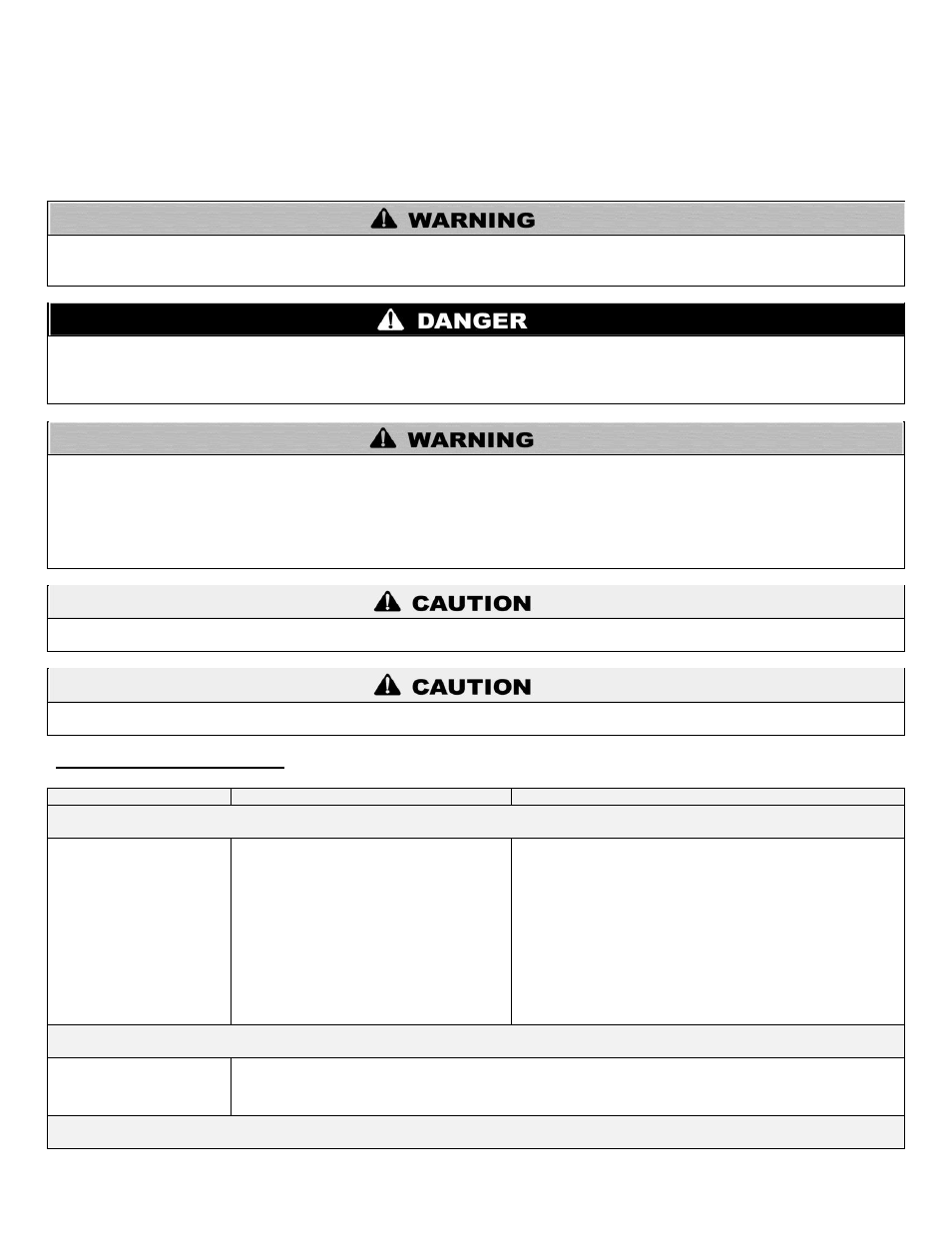
When servicing or replacing any components of this heater, be certain that:
The gas is off.
All electrical power is disconnected.
When servicing or replacing components that are in direct contact with heater water, be certain that:
There is no pressure in the heater. (Pull the release on the relief valve. Do not depend on the pressure gauge reading.
The heater water is not hot.
The electrical power is disconnected.
DO NOT USE THIS APPLIANCE IF ANY PART HAS BEEN SUBMERGED IN WATER. Immediately call a qualified service technician.
The appliance MUST BE replaced if it has been submerged. Attempting to operate an appliance that has been submerged could create
numerous harmful conditions, such as a potential gas leakage causing a fire and/or explosion, or the release of mold, bacteria, or other
harmful particulates into the air. Operating a previously submerged appliance could result in property damage, severe personal injury,
or death.
NOTE: Appliance damage due to flood or submersion is considered an Act of God, and IS NOT covered under product warranty.
This appliance has wire function labels on all internal wiring. Observe the position of each wire before removing it. Wiring errors may
cause improper and dangerous operation. Verify proper operation after servicing.
If overheating occurs, or the gas supply fails to shut off, do not turn off electrical power to the circulating pump. This may aggravate the
problem and increase the likelihood of heater damage. Instead, shut off the gas supply to the heater at the gas service valve.
D. USER INTERFACE DISPLAY
Cascade Control FAULT Codes
SCREEN
DESCRIPTION
POSSIBLE REMEDY
Fault Code EO3
System Sensor Failure
SYS SUPPLY SENSOR
PUMP OFF E03
This screen shows that there is a problem with
the system sensor circuit. The circuit could be
open or shorted. Possible reasons for this error
are:
There is no system sensor connected to the
Master Heater.
The system sensor is faulty.
There is a short circuit in the system sensor
wiring; possibly from a staple placed through
the wire, or damage to the wire causing both
conductors to touch.
The system sensor wiring is open due to defect
or damage.
Disconnect the system sensor from the wiring and measure the
resistance of it. Compare the measured resistance to the table in
this manual to see if it corresponds to the temperature of the sensor.
If the resistance does not agree with the sensor, replace the sensor.
If the sensor is OK, disconnect the sensor wiring from both the
heater and the sensor and check continuity using an ohmmeter.
Repair or replace as necessary.
If this error is present, all heaters in the cascaded group will run and
ignite simultaneously when there is a heat demand. Each heater will
modulate to maintain set point temperature on its own supply
sensor. This code will reset automatically when repair is complete.
This code will not display if system setting function ERROR
SYSTEM SENS is set to OFF.
Fault Code TT
Temperature Blocking TT Demand
TEMPER BLOCKING
PUMP ON TT
This screen shows that there is a demand on the heater, the pump is powered on, and the temperature of the water at
the supply sensor is too high for the heater to ignite. This occurs because the water temperature measured by the
supply sensor is higher than the tank temperature
– ignition diff setting. This message will stay present until the water
temperature measured by the supply sensor is less than the tank temperature
– ignition diff setting.