C. heater test mode, Part 11, Troubleshooting – HTP EL-399NVWH User Manual
Page 63: A. heater error code, B. heater error, C. heater fault, Part 11 – troubleshooting
63
LP- 346 REV. 3.20.14
Press the
▼ key once.
HEATER 2 0%
HEATER 3 0%
This screen shows the current cascade power demand output on a per connected heater basis for heaters
addressed as 2 and 3.
Press the
▼ key once.
HEATER 4 0%
HEATER 5 0%
This screen shows the current cascade power demand output on a per connected heater basis for heaters
addressed as 4 and 5.
Press the
▼ key once.
HEATER 6 0%
HEATER 7 0%
This screen shows the current cascade power demand output on a per connected heater basis for heaters
addressed as 6 and 7.
Table 25
– Cascade Menu
C. HEATER TEST MODE
This function is intended to simplify the gas adjustment. Listed in Table 26 are the
recommended combustion settings for the gas type selected to run the heaters.
Automatic modulation does not take place when the controller is in test mode.
However, the heaters will modulate down if the program set point is reached while running in test mode. It is recommended you have
the largest load possible to create a heat demand so the test mode operation will not be interrupted. To enter test mode, press the
▲
and
▼ arrow keys simultaneously. NOTE: The heater will automatically exit test mode after 20 minutes of operation.
To leave service mode, press the ▲ and ▼ keys simultaneously.
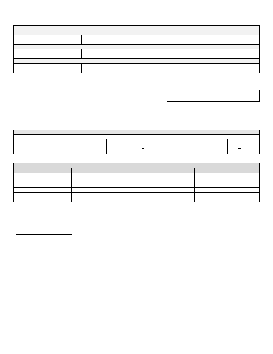
Table 26
– Combustion Settings, All Models
ELITE VWH FAN SPEEDS
MODEL
IGNITION
MIN
MAX
EL-80 VWH
3000
1700
4600
EL-110 VWH
3800
1700
4950
EL-150 VWH
3800
1700
5200
EL-220 VWH
3000
1450
4900
EL-299/301 VWH
3000
1450
5000
EL-399 VWH
3000
1600
6650
Table 27
PART 11 – TROUBLESHOOTING
A. HEATER ERROR CODE
If any of the sensors detect an abnormal condition, or an internal component fails during the operation of the heater, the display may
show an error message and error code. This message and code may be the result of a temporary condition, in which case the display
will revert to its normal readout when the condition is corrected, or it may be a condition that the controller has evaluated as not safe to
restart the heater. In this case, the heater control will be locked out, the red FAULT light will be lit, and the mes
sage “LOCKOUT” will be
displayed on the readout on the lower line.
The Heater will not start until a qualified technician has repaired the heater and pressed the RESET button for more than 1 second. If
there is an error message displayed on the readout, and the mes
sage “LOCKOUT” is not displayed and the FAULT light is not lit, then
the message is the result of a temporary condition and will disappear when the problem corrects itself.
IMPORTANT NOTE: If you see error messages on your display readout, call a technician immediately, since the message may indicate
a more serious problem will occur soon.
B. HEATER ERROR
When an error condition occurs, the controller will display a description and code on the display readout. These error messages and
their recommended corrective actions are described in Section D.
C. HEATER FAULT
1. When a fault condition occurs, the controlle
r will illuminate the red “FAULT” indication light and display a fault message in the screen.
The alarm output will also activate. Most fault conditions cause the CH pump to run in an attempt to cool the heater.
SERVICE RUN
3400 RPM
PUMP ON
4:49P
COMBUSTION SETTINGS ON ALL MODELS
Natural Gas
Propane LP
Fan Speed
Low
Ignition
High
Low
Ignition
High
Carbon Monoxide PPM
5
– 50
60 - 100
< 150
5
– 50
60 - 100
< 150
Carbon Dioxide (CO
2
)
8 - 10%
8 ½ - 10 ½%
8 ½ - 10 ½%
9 - 10 ½%
9 ½ - 11%