Part 10, Start-up procedures for the installer, A. heater control status menu – HTP EL-399NVWH User Manual
Page 61: Part 10 – start-up procedures for the installer
61
LP- 346 REV. 3.20.14
PART 10 – START-UP PROCEDURES FOR THE INSTALLER
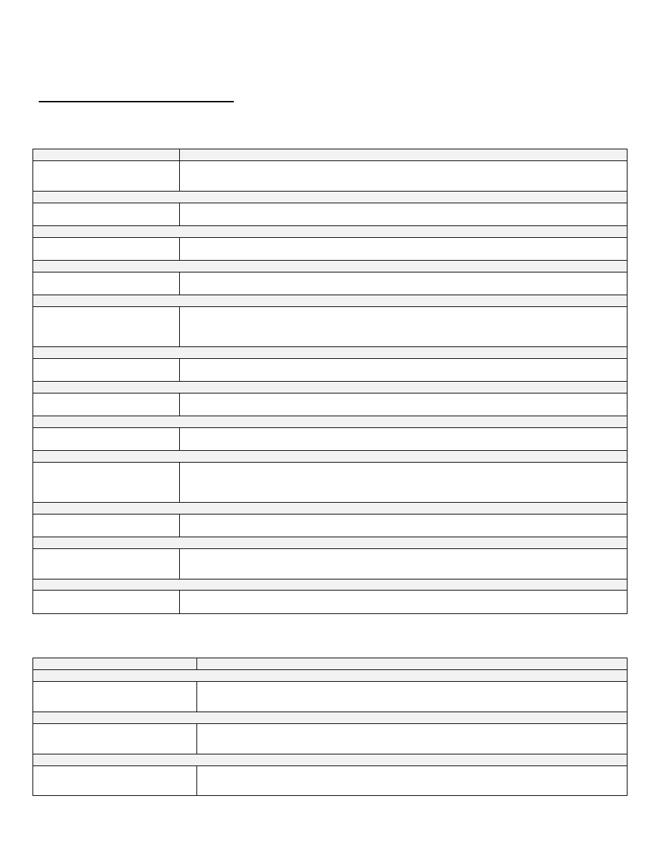
A. HEATER CONTROL STATUS MENU
The heater control also has the ability to review the status of the system. To access the status screens, simply press the right arrow .
Once the first value is displayed, press the up arrow
▲ or down arrow ▼ to access additional information. At any point you may press
the RESET button to exit the status screen.
SCREEN
DESCRIPTION
SUPPLY SEN 180
o
F
RETURN SEN 150
o
F
This screen is displayed after pressing the key as described above. This shows the actual temperature that the
supply and return sensors are measuring. NOTE: If the heater is configured to use a 0
– 10 volt input, the return
sensor is disabled and the second line of the display will be blank.
Press the
▼ key once.
NA NA
NA
SUPPLY SEN
122
o
F
The actual temperature measured by the supply sensor is displayed on the bottom.
Press the
▼ key once.
0-10 SIGNL ON
*
Shows if 0
– 10 volt is enabled.
Press the
▼ key once. (This screen will appear only when set in Master Heater mode).
CAS SET 190
o
F
SYSTEM 112
o
F
This screen displays the cascade set point (maximum 190
o
F) on the top line. The system sensor value reading is
on the second line. The control will cascade the heaters up to this set point depending on demand.
Press the
▼ key once.
TANK SET 120
o
F
RET / TANK OFF
This screen displays the current tank temperature set point on the top line. The actual temperature measured by
the tank or return line sensor (HTP 7250P-325) is displayed on the bottom line. If a mechanical aquastat is used in
place of the recommen
ded sensor, the second line will display ‘OFF’ in place of the temperature if the aquastat
measures close to its set temperature, or ‘ON’ in place of the temperature if the aquastat temperature is too low.
Press the
▼ key once.
NA 11
o
F
FLUE 95
o
F
The second line displays the current flue temperature of the heater.
Press the
▼ key once.
FLAME 0.0uA
FAN SPEED 3497 RPM
This screen displays the heater flame current on the top line. The second line displays the fan speed in the heater.
Press the
▼ key once.
0-10 V 0.0 V
*
The top line displays the voltage on the optional input. This voltage is only relevant if an external 0-10 volt signal is
being used to control the heater.
Press the
▼ key once.
BUS COMM NO CONN
This display shows the status of the communication bus between multiple heaters. If the heater is in a single
heater configuration, the display will show ‘NO CONN’. If the heater is used in a multiple coiler configuration, is the
Master Heater, and other heaters are connected to the communication bus and powered, this screen will show the
address of each heater connected to the bus.
Press the
▼ key once.
POWER ON 0H
CH ON 0H
The top line of this display indicates the amount of hours the heater has had power applied to it over its life. The
second line is not applicable.
Press the
▼ key once.
VWH ON 0H
0H
GOOD IGNIT
1X
The top line of this display indicates the amount of hours the burner has been on for hot water demand in the life
of the heater. The second line indicates how many times the burner has successfully ignited in the life of the
heater.
Press the
▼ key once.
SYS CH ON 0h
SYS VWH ON 0h
The top line is not applicable. The second line registers system pump hours on cascade master ONLY.
Table 23 - Heater Control Status Menu Screens
The following 10 screens display the last ten heater lockout faults. The faults are displayed from most recent to oldest by depressing
the
▼ key.
SCREEN
DESCRIPTION
Press the
▼ key once.
FAULT HISTORY 1
07/27/2009 Mo 5:19A
This screen displays the last lockout fault of the heater controller. The top line will alternate between the
words ‘FAULT HISTORY’ and the actual fault encountered. The bottom line displays the date and time the
fault occurred.
Press the
▼ key once.
FAULT HISTORY 2
08/28/2009 Fr 5:19A
This screen displays the second oldest lockout fault that occurred in the heater controller. The top line will
alternate between the words ‘FAULT HISTORY’ and the actual fault encountered. The bottom line will display
the date and time that the fault occurred.
Press the
▼ key once.
FAULT HISTORY 3
08/28/2009 Fr 5:19A
This screen displays the third oldest lockout fault that occurred in the heater controller. The top line will
alternate between the words ‘FAULT HISTORY’ and the actual fault encountered if one has occurred. The
bottom line displays the date and time a fault occurred.