HTP EL-399NVWH User Manual
Page 49
49
LP- 346 REV. 3.20.14
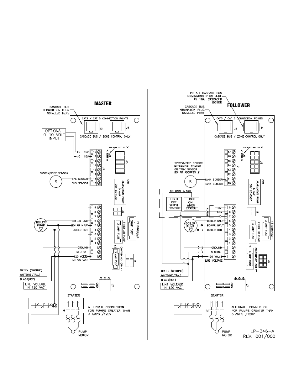
2. An alarm bell or light can be connected to the alarm contacts of the follower heater. The normally closed alarm contact may be used
to turn a device off if the heater goes into lockout mode. The alarm contacts are rated 5 amps at 120 VAC.
To connect an alarm device, connect the power for the device to the ALARM COM terminal. Connect the alarm device hot wire to the
ALARM NO terminal. Connect the neutral or return of the alarm device to the neutral or return of the power for the alarm device.
To connect a device that should be powered off during a heater lockout condition, follow the same instructions as above except use the
ALARM NC terminal rather than the ALARM NC terminal.
Note that in a cascade system the alarm output of the heater addressed as #1 will also be active if the master heater has a lockout
condition. The alarm output of heaters addressed as 2-7 will only activate an alarm if a lockout condition occurs on that specific heater.
Figure 29
– Cascade Wiring