Part 7, Field wiring, A. installation must comply with – HTP EL-399NVWH User Manual
Page 45: B. field wiring terminations, C. field wiring, D. line voltage wiring for standard heater, E. alarm connections, Part 7 – field wiring
45
LP- 346 REV. 3.20.14
PART 7 – FIELD WIRING
ELECTRICAL SHOCK HAZARD - For your safety, turn off electrical power supply at service entrance panel before making any
electrical connections. Failure to do so can result in severe personal injury or death.
Wiring must be N.E.C. Class 1.If original wiring supplied with the heater must be replaced, use only TEW 105
o
C wire or
equivalent.Heater must be electrically grounded as required by National Electrical Code ANSI/NFPA 70
– Latest Edition.
To ease future service and maintenance, label all wires. Wiring errors can cause improper and dangerous operation, and result in
substantial property damage, severe personal injury, or death.
A. INSTALLATION MUST COMPLY WITH:
1. National Electrical Code and any other national, state, provincial or local codes or
regulations.
2. In Canada, CSA C22.1 Canadian Electrical Code Part 1, and any local codes.
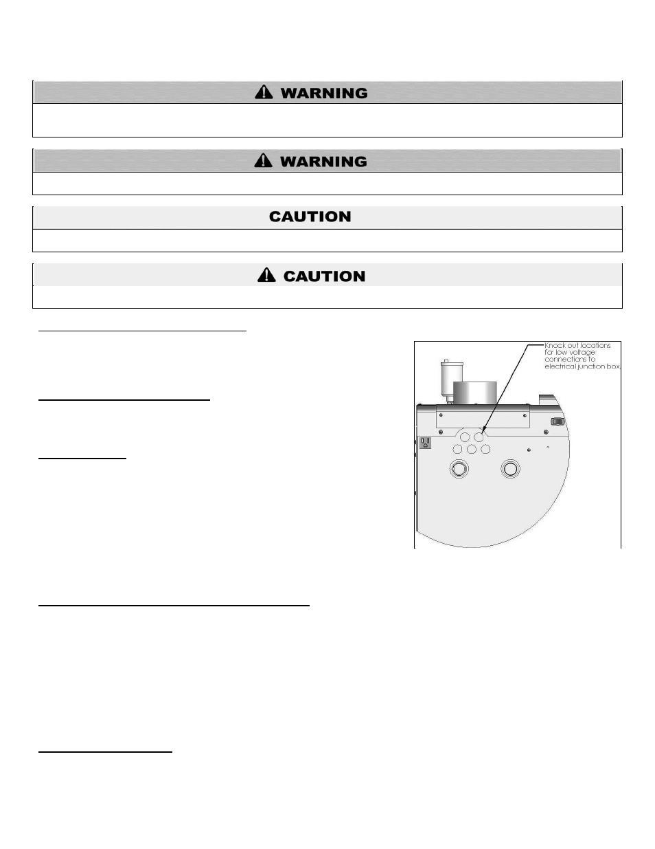
B. FIELD WIRING TERMINATIONS
All connections made to the heater in the field are done inside the electrical junction
box located on the left side of the unit. Multiple knockout locations are available to
route field wires into and out of the electrical junction box.
C. FIELD WIRING
The control used in the heater is capable of directly controlling 1 pump in standard
mode and 2 pumps when configured as a cascade master heater. As a standard unit,
each pump can provide a maximum of 3 amps at 120 volts. If a pump requires more
than this amount of power, an external contactor or motor starter is needed. If the
heater is configured as a cascade master, the system pump output is a dry contact
output capable of switching 5 amps at 120 volts, in addition to the heater pump output
sourcing 4 amps each.
The electrical junction box has separate, clearly marked terminal strips for line voltage
and low voltage wiring. Special jacks are provided for trouble-free cascade system
wiring using standard CAT3 or CAT5 patch cables.
D. LINE VOLTAGE WIRING FOR STANDARD HEATER
NOTE: A termination plug is included in the CAT 3 / CAT 5 Bus Connection Point, labeled J3 in Figure 23. DO NOT REMOVE THIS
PLUG! Doing so will affect heater operation and void warranty.
1. Connect the incoming power wiring to the line voltage terminal strip in the electrical junction box at terminals 120V, Neutral, Ground
(shown in Figure 26).
2. A line voltage fused disconnect switch may be required, externally mounted and connected according to local codes that may apply.
3. Connect the heater pump as shown in Figure 26 to the terminals marked 1
– (HOT), 2 – (NEUT), and 3 – (GND). The connections
shown are suitable for a maximum continuous pump draw of 3 amps at 120 volts. If the pump requires more current or voltage than the
120 volts supplied, an external motor starter or contactor will be required.
E. ALARM CONNECTIONS
The control includes a dry contact alarm output. This is an SPDT circuit, rated at 5 amps at 120 volts. This contact can be used to
activate an alarm light or bell or notify a building management system if the heater goes into a lockout condition. The circuit between
the ALARM COM and NC terminals is closed during normal operation and the circuit between ALARM COM and NO is open during
To avoid electrical shock, turn off all power to the appliance prior to opening an electrical box within the unit. Ensure the power remains
off while any wiring connections are being made. Failure to follow these instructions could result in component or product failure,
serious injury, or death. Such product failure IS NOT covered by warranty.
Figure 25
– Knockout Locations