Multiple boiler manifold piping – HTP EL-399NVWH User Manual
Page 20
20
LP- 346 REV. 3.20.14
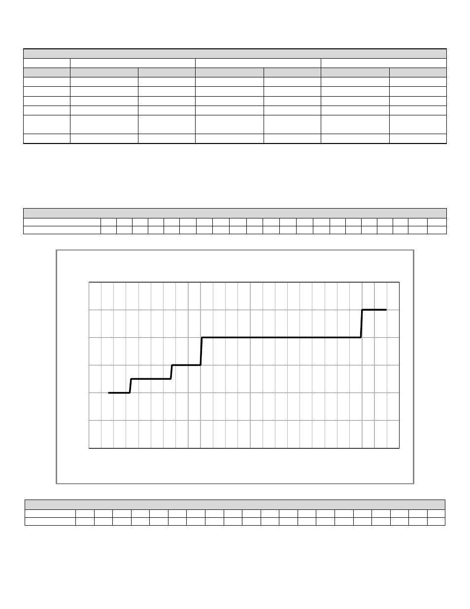
The chart below represents the combined flow rates and pipe sizes when using multiple heaters to design the manifold system for the
primary circuit. To size, simply add up the number of heaters and the required flow rates for the system design temperature.
Example: (5) EL-220 Heaters® with a design of 20°
Δt degree temperature rise with each heater having an individual flow rate of 22
GPM. To correctly size the manifold feeding these (5) heater
s you would need a pipe size of 4”.
MULTIPLE HEATER MANIFOLD PIPING
Flow Rate (GPM)
16
22
24
30
32
33
40
44
45
48
50
55
60
66
75
80
85
88
90
100
110
Pipe Dia. (Inches)
2
2
2
2
2
2½
2½
2½
2½
2½
2½
2½
2½
2½
3
3
3
3
3
3
4
Table 9
Figure 6
MULTIPLE HEATER MANIFOLD PIPING
Flow Rate (GPM)
120
132
150
160
170
179
200
210
239
240
250
255
300
340
350
400
425
510
595
680
Pipe Dia. (In.)
4
4
4
4
4
4
4
4
5
5
5
5
5
5
5
5
5
6
6
6
Table 10
0
1
2
3
4
5
6
0
50
100
150
200
250
Pip
e
Di
am
e
te
r
Si
ze
(
In
ch
e
s)
Combined Boiler Water Flow (GPM)
Multiple Boiler Manifold Piping
SYSTEM TEMPERATURE RISE CHART
Model
20°Δt
25°Δt
30°Δt
Ft / Friction
Flow Rate
Ft / Friction
Flow Rate
Ft / Friction
Flow Rate
EL-80
17’
8 GPM
10’
6.6 GPM
7’
5.3 GPM
EL-110
25’
11 GPM
17’
9.1 GPM
12’
7.3 GPM
EL-150
27’
15 GPM
17’
12.5 GPM
12’
10 GPM
EL-220
19’
22 GPM
13’
18.3 GPM
12’
14.6 GPM
EL-299
EL-301
29’
29 GPM
18’
24.5 GPM
13’
20 GPM
EL-399
39’
39 GPM
19’
32.5 GPM
13’
26 GPM
Table 8