Warning – Harrington Hoists and Cranes RH - Advantage Wire Rope Hoist User Manual
Page 21
21
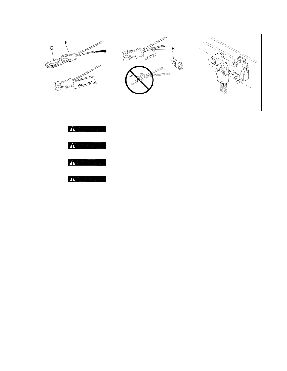
Figure 3-19
Install Wire Rope
on Terminal Head
Figure 3-20
Install Rope
Clamp
Figure 3-21
Install Terminal
Head
3.6.2
Adjusting the Limit Switches:
1)
WARNING
The maximum upper and lower Limit Switch (B, C) adjustments are marked in red
on the Section Bar (D). NEVER adjust the limit switches past the red marks (
Figure 3-22
).
2)
WARNING
The upper Limit Switch (B) MUST be adjusted to prevent the collision of the load
and/or Bottom Block with any part of the hoist, structure or girder(s) (
Figure 3-23
).
3)
WARNING
NEVER adjust the upper Limit Switch (B) so that the Bottom Block can rise above
the position dictated by dimension “E” in
Table 2-5
.
4)
WARNING
The adjustment of the lower Limit Switch (C) MUST always ensure a minimum of 3
turns of wire rope completely wound on the drum (
Figure 3-26
).
5) The lower Limit Switch (C) MUST be adjusted so that the hook can be lowered fully for the application,
WITHOUT the Hook/Bottom Block resting on the floor causing a slack condition in the wire ropes
(
Figure 3-24
).
6) Lower Limit Switch (C) Setting:
+ Press the down button on the pendant and carefully lower the Hook to the position of maximum
descent for the application.
+ Loosen the screws (A) so that the lower Limit Switch (C) can freely run along the Section Bar (D)
then position the Switch so that it engages the striker on the rope guide. Secure the Switch in
position by tightening the Screws (A) (
Figure 3-25
).
+ Carefully verify the correct activation of the lower Limit Switch (C) by lowering the Hook several
times and readjust the Lower Limit Switch (C) as necessary.
7) Upper Limit Switch (B) Setting:
+ Carefully raise the Hook until it is at the uppermost position dictated by dimension “E” in
Table 2-5
.
+ If the upper Limit Switch activates before the Hook reaches the uppermost position, measure how
far the Hook still needs to travel, then multiply the distance by 4. Adjust (increase) the length of
rope that extends beyond the Terminal Head by the resulting amount (Refer to
Section 3.6.1)
.
+ Loosen the screws (A) so that the upper Limit Switch (B) can freely run along the Section Bar (D)
then position the Switch so that it engages the striker on the rope guide. Secure the Switch in
position by tightening the Screws (A) (
Figure 3-25
).
+ Carefully verify the correct activation of the upper Limit Switch (B) by raising the Hook several times
and readjust the Upper Limit Switch (B) as necessary.