Danger – Harrington Hoists and Cranes RH - Advantage Wire Rope Hoist User Manual
Page 19
19
3.5.5 Installing
Pendant
1) Refer to
Figure 3-16
, the wiring diagram and the interconnection diagram provided with the Hoist.
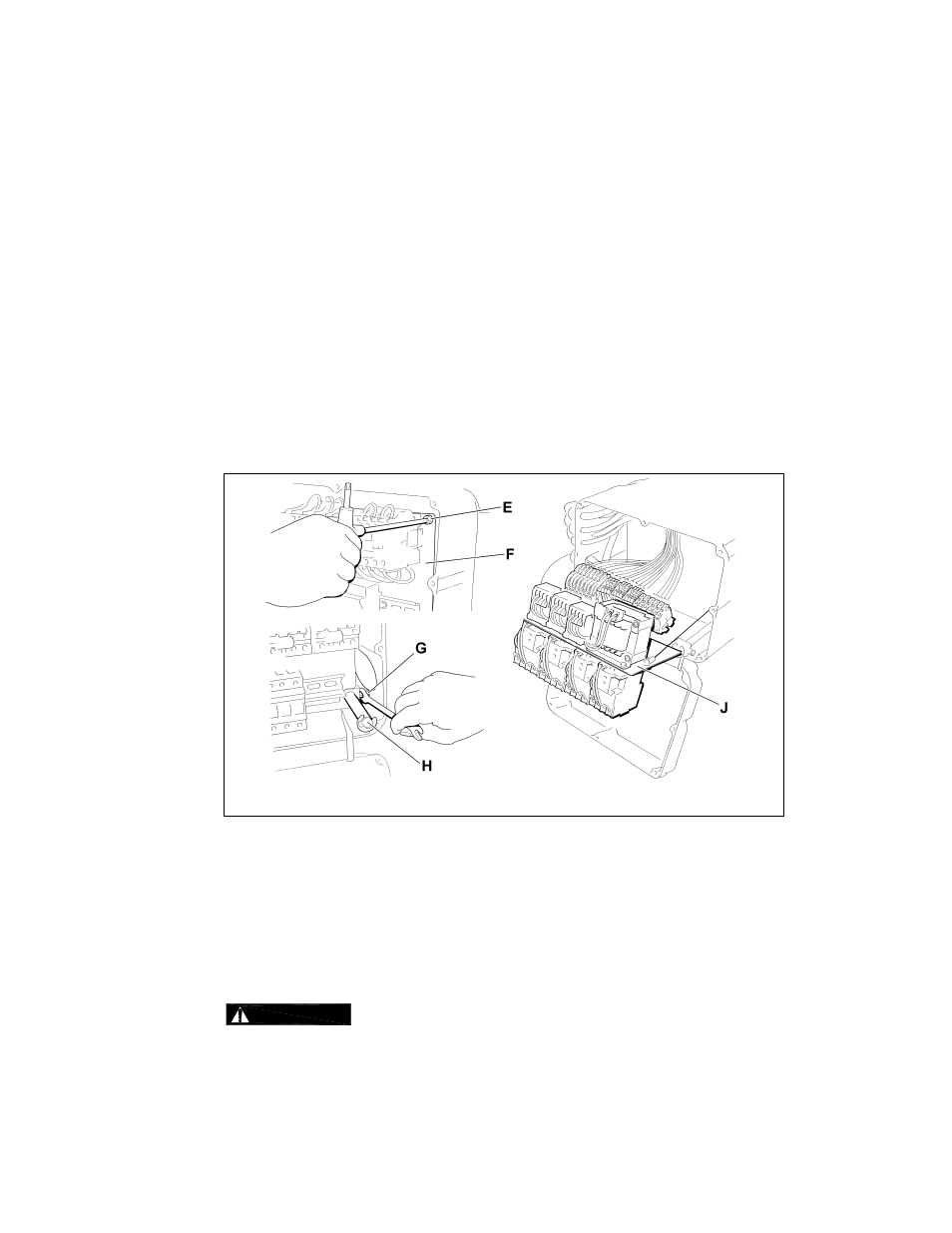
2) Remove Control Cover (A).
3) Access to Terminal Strip: For hoists with the integral electrical enclosures (plastic cover), the Terminal
Strips are located on the back side of the Panel (F). Gain access by removing the Socket Bolts (E)
securing the Panel (F), loosening the Set Bolts (G) on the Support Bars (H), then slide and rotate the
Panel (F) forward.
4) Loosen the Cable Fitting (C) located on the left side of the electrical enclosure and insert the pendant
cord. Pull through enough cord to reach the terminals then securely tighten the Cable Fitting (C).
5) Attach a strain relief cable or chain between the pendant and hoist. The cord or chain should attach to
the Small plate or eyebolt located at the bottom of the electrical enclosure.
6) Connect the individual pendant leads to the correct terminals as shown on the interconnection diagram.
Make sure the terminals are securely tightened and each lead is completely isolated.
7) Reattach the Control Panel (F) and replace the Control Cover (A) or close the metal electrical
enclosure. Be careful to not damage the seal or sealing surfaces and make sure to securely tighten all
fasteners or latches.
Figure 3-16
Installing Pendant
3.5.6
Connection to Electrical Power Source - The 3 power leads of the Power Supply Cable (normally red,
white, and black wires) should be connected to an Electric Power Disconnect Switch or Circuit Breaker.
This connection should be made so that the hoist is phased properly. Refer to
Section 3.7.4
for
instructions on how to check for correct power supply phase connection.
3.5.7
Fuse/Breaker Capacity - The trolley and hoist's power supply should be equipped with overcurrent
protection such as fuses, which should be selected for 110% to 120% of total listed full load amperage,
and should be dual element time-delay fuses. For the total full load amperage draw, add the amperage
draws shown on the motor nameplates of ALL lifting and traversing motors.
3.5.8
DANGER
Grounding - An improper or insufficient ground connection creates an electrical
shock hazard when touching any part of the hoist or trolley. In the Power Supply Cable the ground wire
will be either Green with Yellow stripe or solid Green. It should always be connected to a suitable
ground connection. Do not paint the trolley wheel running surfaces of the beam as this can affect
grounding.