Harrington Hoists and Cranes CF Hand Chain Hoist User Manual
Page 27
27
NOTE: The pawl pin is fixed with the U nut [25].
11) Unscrew four socket bolts [22, 22-A] connecting body A [10] and B [11].
NOTE: Four socket bolts are fixed with U nuts [23] on the body B side.
12) Separate the body A [10] and B [11].
13) Take ball bearing A [15] and C [17-A] out of the body A [10] (only if bearing needs replaced).
14) Remove the top hook [1] and top pin [3] from the body B [11].
15) Remove pinion [14], chain guide [20] (or guide rollers [20-A]), stripper [21], tail pin [40], and load
chain [42].
16) Remove the frame [13].
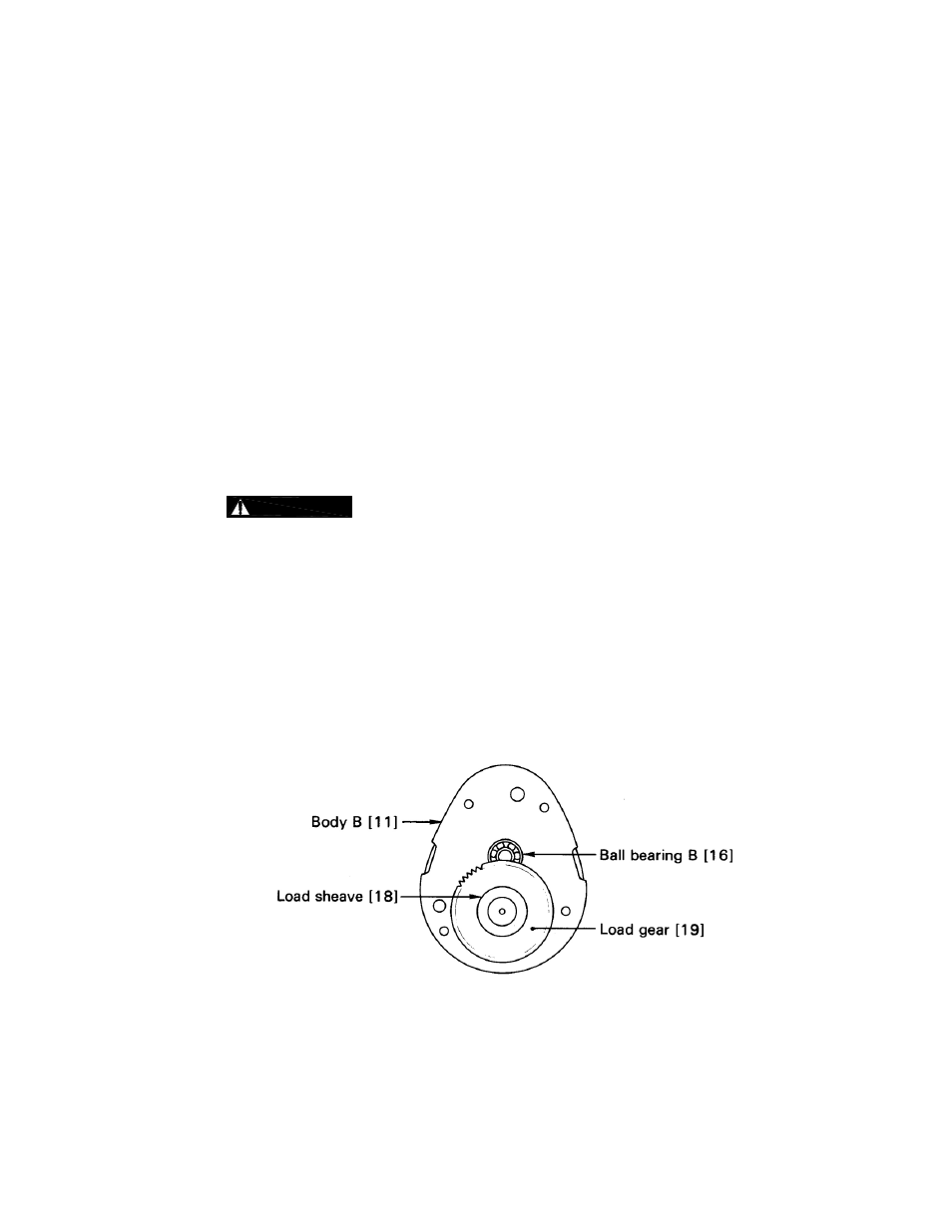
17) Take load sheave [18] out of the load gear [19].
18) Remove the load gear [19].
19) Unscrew tap socket bolt [41] from the body B [11].
20) Pull split pin [9] out of the slotted nut [8] and remove the slotted nut and chain pin [7] from the
bottom hook [4].
6.4
Hoist Assembly
6.4.1
Inspect and replace any worn or damaged parts per Table 5-3.
Secure all nuts, bolts and split pins firmly.
Replace all split pins and retaining rings.
6.4.2
Assembly
1) Wipe off old grease from the body B [11] and frame [13].
2) Apply new grease to the ball bearing B [16] and C [17] on the body B [11].
3) Insert load sheave [18] into the load gear [19] and put them together on the ball bearing C [17].
4) Apply new grease to the load gear [19].
5) Put frame [13] on the body B [11] according to pattern.
Figure 6-2 Load Gear Assembly