On the front of the analog smart brick – Gilderfluke&Co Analog Output Smart Brick (ver 2.nn w/Eprom memory) User Manual
Page 7
On the Front of the Analog Smart Brick:
A) RS-422 Serial Port: This is used to configure the BS-ANA. It is compatible with all of the RS-422
Serial Ports used on Gilderfluke & Company products.
As a convenience, the four active lines on this connector are bussed to the backplane of
the card cage. This allows you to communicate to a whole card cage full of BS-ANAs, Smart
Brick Brains, Electronic FeedBack (EFB) Smart Bricks and other cards through the connector on
any single card. They just need to be set to different addresses. If desired, permanent connec-
tions can be made on the back of a card cage.
The serial data signals from the BS-ANA are brought out on a six position RJ-11 (modular
telephone style connector). Facing the end of the cable with the release latch upwards, its
pin out is as follows:
COLOR
SIGNAL NAME:
LEFT
#1 white
Signal Ground
#2 black
- Serial data out from card
#3 red
+ Serial data out from card
#4 green
- Serial data in to card
#5 yellow
+ Serial data in to card
RIGHT
#6 blue
Signal Ground
PC and Compatible Connections: If you are only talking to a single BS-ANA and your wire
length is short, you may be able to simply cross wire the RS-232 serial port on your PC to talk
to the BS-ANA. This does not work on all PCs, as some donÕt swing their RS-232 outputs as far as
they should. If it does not work with your PC, you may need to get a RS-232 to RS-422 con-
verter to talk to the BS-ANA. To cross wire the RS-422 / RS-485 signals from the BS-ANA to the
RS-232 serial port of an IBM compatible, cross connect the signals as follows:
DB-25
DE-9
Signal
Signal from/to BS-ANA
2
3
DATA OUT
- Serial data into card (#4 green)
3
2
DATA IN
- Serial data out from card (#2 black)
7
5
GROUND
Signal Ground (#1 white or #6 blue)
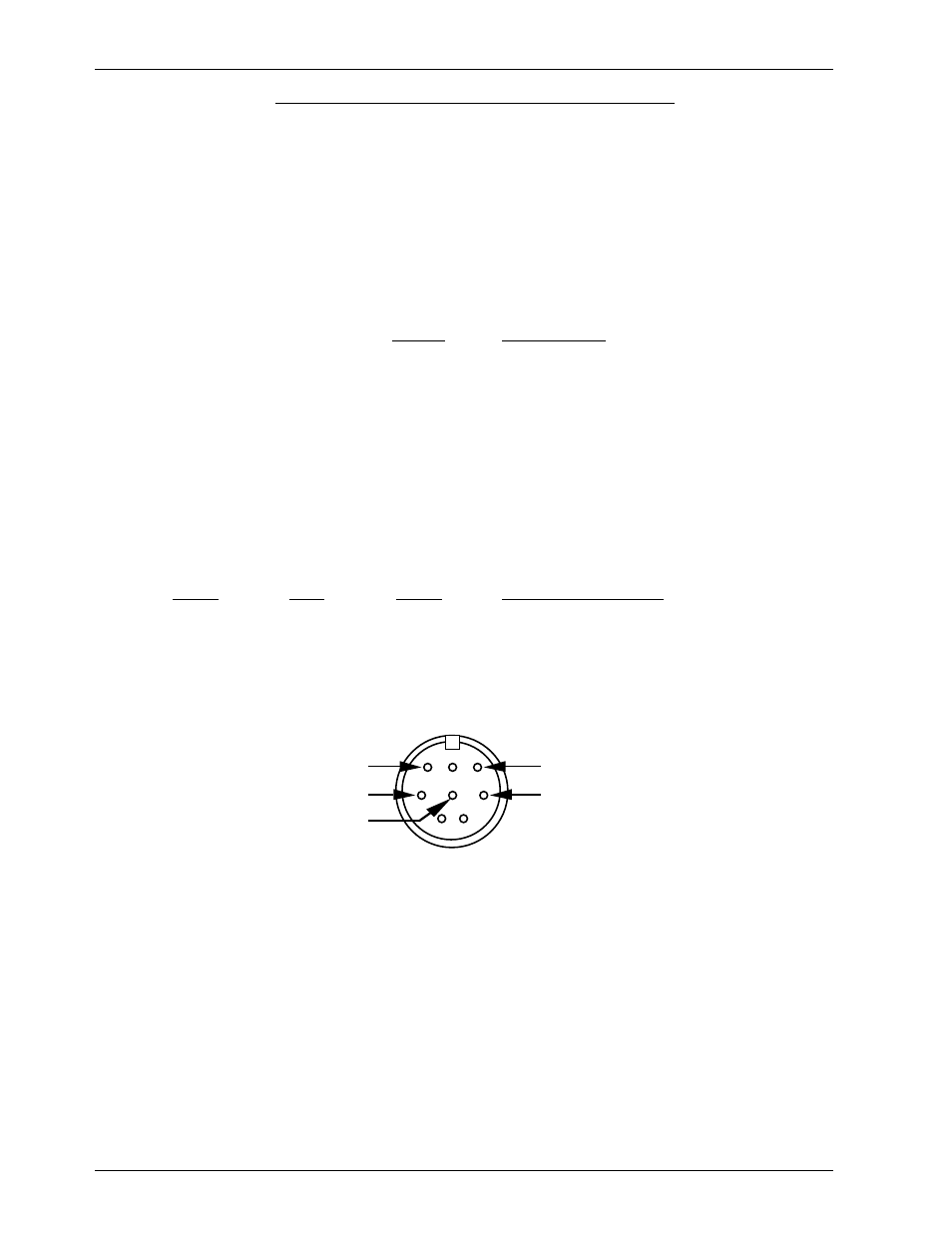
Apple Macintosh Connections: Apple Macintosh computers have true RS-422 serial ports
built in. To connect to the BS-ANA, the pin out is as follows (view is of male connector facing
the end of the cable):
to + serial data in to card (#5 yellow)
to - serial data in to card (#4 green)
1
2
3
4
5
6
7
8
from - serial data out from card (#2 black)
from + serial data out from card (#3 red)
signal ground (#1 blue or #6 white)
The BS-ANA expects to see the serial data in the following format:
ONE START BIT
EIGHT DATA BITS
ONE STOP BIT
Unlike many of the products manufactured by Gilderfluke & Company, the BS-ANA re-
sponds only to the command to enter the configuration mode, download/upload configura-
tion and status enquiries. It will ignore all other commands, which allows it to share the same
RS-422 serial line with additional BS-ANAs, Digital Audio Repeaters, Smart Brick Brains and other
serially controlled devices. The only requirement is that each unit be addressed to a different
location.
B) DMX-512 Data In/Out: Five pin MiniDIN connector. The BS-ANA will stop listening to the Smart
Brick network whenever there is a DMX-512 signal present on this input. If JP-1 is in the 'DMX'
position, then the two received data lines on this connector will be attached to pins 11 and
G
ILDERFLUKE
& C
O
.¥ 205 S. F
LOWER
S
T
. ¥ B
URBANK
, CA 91502 ¥ 818/840-9484 ¥ 800/776-5972 ¥
FAX
818/840-9485
3 of 24