Sonnet Technologies Tempo Ultra ATA66 Host Adapter User Manual
Page 35
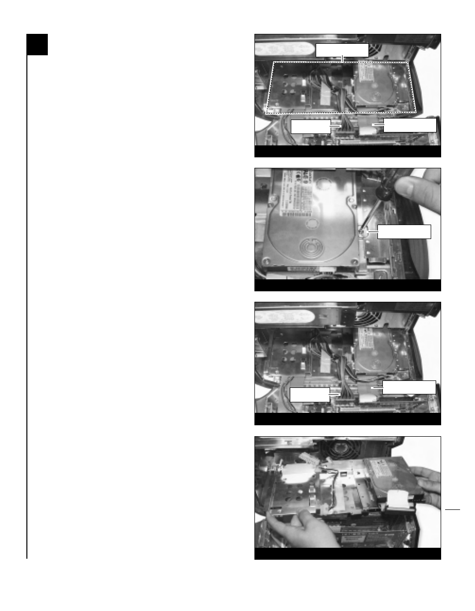
6. Locate the lower internal expansion bay area
of the computer (Figure 4). For specific
details, refer to your computer’s user manual.
For Power Macintosh G3 Blue & White
built after June 1999 and G4 Graphite
models: There are three drive carriers located
on the floor of the cabinet. Depending on your
computer model, you may need to disconnect
the power cord bundle and internal hard drive
ribbon cable (Figure 4) prior to removing a
carrier. To mount a drive to a drive carrier,
locate an unoccupied carrier and remove the
single attachment screw found at the rear of
the carrier. Detach and remove the carrier from
the computer.
For Power Macintosh G3 Blue & White
models built before June 1999: There is
a single drive sled that occupies the floor of
the cabinet. To mount a drive to the drive sled,
you will need to temporarily remove the drive
sled from the computer. First, remove the
drive sled attachment screw next to the
internal hard drive (Figure 5). Then, discon-
nect the power cord bundle and internal hard
drive ribbon cable from the logic board
(Figure 6). Once all the cables are clear,
CAREFULLY remove the drive sled from the
computer (Figure 7).
6-3
Figure 4
Figure 5
internal expansion
bay area
internal hard drive
ribbon cable
power cord
bundle
drive sled
attachment screw
Figure 6
Figure 7
internal hard drive
ribbon cable
power cord
bundle