Ronan X71 User Manual
Page 7
M E C H A N I C A L
The X71 Mosaic Graphic System is assembled from
12″ x 12″ (304.80 mm x 304.80 mm) reinforced fiber-
glass matrix grids to the customer’s specified size. The
assembled grids are mounted into a heavy steel frame
with cross beam support on each corner of each 12″
(304.80 mm) matrix grid. The steel frame is selected
from the two available depths based on the overall size
of the graphic. The accurate panel cutout dimensions
are supplied with the process layout approval drawings
to allow preparation of the control or display panel.
M O U N T I N G
The X71 graphic assembly is fed through the panel
cutout from the front of the panel and clamped from
the rear with the furnished removable clamp assem-
blies. The maximum panel thickness allowed with the
standard clamping assemblies is 1″ (25.40 mm).
Clearance behind the graphic is based on the depth
of the custom equipment mounted in the graphic as
well as optional termination facilities, connectors, or
serial input annunciators.
E L E C T R I C A L
The indicators, control switches, push buttons,
parameter displays, or other equipment required may
be factory wired to terminals mounted to the rear of
the mechanical structure. The indicators and/or
window type lamp cabinets may be controlled from
conventional solid state alarm logic or X110 Serial
Input Annunciator Controller(s). The X110 may be
integral mounted to the rear of the graphic and factory
wired to the indicators. Optionally, Ronan may provide
multiconductor cables wired to the indicators in the
graphic, and multi-pin connectors for interface to the
remote mounted X110 controllers.
S P E C I A L E N C L O S U R E S
The X71 graphic may be mounted into custom
fabricated enclosures. The enclosures are manufactured
from stainless steel or from cold-rolled steel and
painted to customer specified color. They are sized to
accommodate the graphic, termination facilities and/
or serial input annunciator controllers.
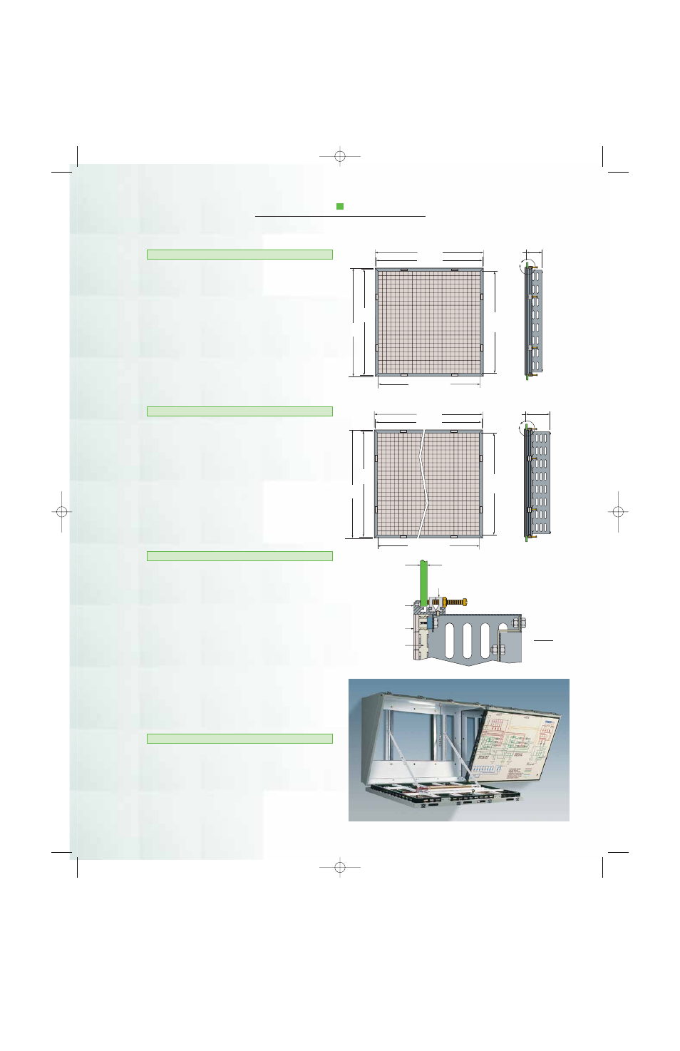
S P E C I F I C A T I O N S
A Overall
B Cutout
A
Overall
B
Cutout
H
Graphic
Height
H Graphic Width
A
3.65"
(92.71 mm)
A Overall
B Cutout
A
Overall
B
Cutout
H
Graphic
Height
H Graphic Width
A
5.65"
(143.51 mm)
.38" (9.65 mm)
Maximum Thickness
Mounting Panel
Mounting Clamp Assembly
Maximum 12.00" (304.80 mm)
Spacing
Frame
Extrusion
Tile
Grid
A Overall = Graphic H or W x .0015″ (.0381 mm) + Graphic H or W + 1.50″ (38.10 mm)
B Cutout = A Overall – .62″ (15.75 mm)
7
Detail A
X71 Brochure.fix 10/13/01 6:27 PM Page 6