Ronan X16PDM User Manual
Page 26
Rev 1.0 Series X11CA Hardware Manual
2. X11CA Hardware Setup
Hardware Control-© 2002 Ronan Engineering
22
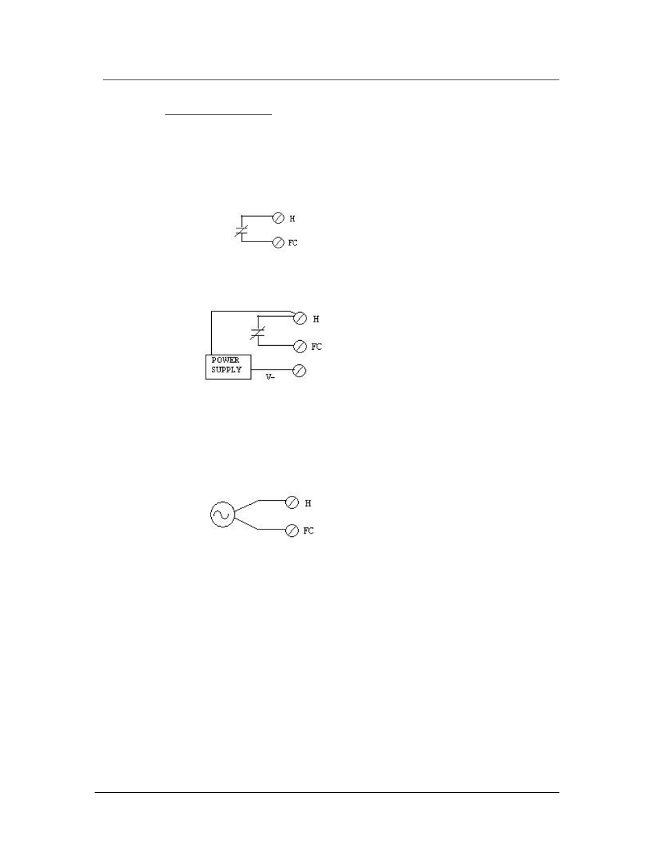
Alarm Terminal Inputs
Two basic types of terminal contacts are available.
i. Dry contact.
Figure 2-20. With 24Vdc
system power
Figure 2-21. With 48Vdc,
5Vdc, 10Vdc, 125Vdc FC
Source
FC source must be common to
the system FC.
ii. Opto-Coupled (Live contact)
Figure 2-22. With FC source
24 Vdc/Vac, 48Vdc/Vac,
120/Vac
Each active alarm input must be wired to a customer’s sensing device to set
its alarm condition as either open or closed. The terminals on the alarm
system for each alarm input are marked H and FC. The H terminal in the
standard alarm system is the main system voltage that is supplied via a pull-
up resistor on each alarm point. Each alarm input module is provided with a
separate H terminal. When using a common H, it is important to jumper
together the H terminals of the respective alarm cabinet modules to provide
the correct amount of current source to the field contact.