Ronan X16PDM User Manual
Page 15
Rev 1.0 Series X11CA Hardware Manual
2. X11CA Hardware Setup
Hardware Control-© 2002 Ronan Engineering
11
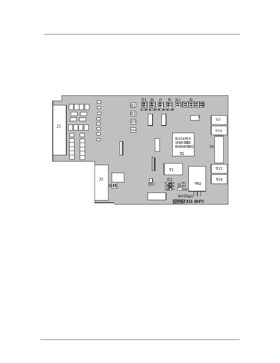
2.2 X11CA Alarm Module: Part NO. X11-1047
Figure 2-7 X11-1047C Module
2.2.1 Power Sources
The external 24 VDC power is supplied to the V+ jumper connector J5 (pin
7,15) and to the V- jumper connector J5 (pin 8,16) on the PC board.
The voltage regulator, VR2, and two resistors, R59 and R63, on the board
reduce the voltage down to 5 VDC.
The electrolytic capacitor, C32, and two ceramic capacitors, C17 and C19,
keep the voltage constant for load variations and voltage transients.