Wiring diagrams, Terminal designations, Dip switch options – Robertshaw 300-206 User Manual
Page 2: Specifications, Removing the thermostat from the subbase, Replacing the thermo- stat on subbase, Thermostat cover lock, Thermistor mounting instructions, Single transformer two transformers
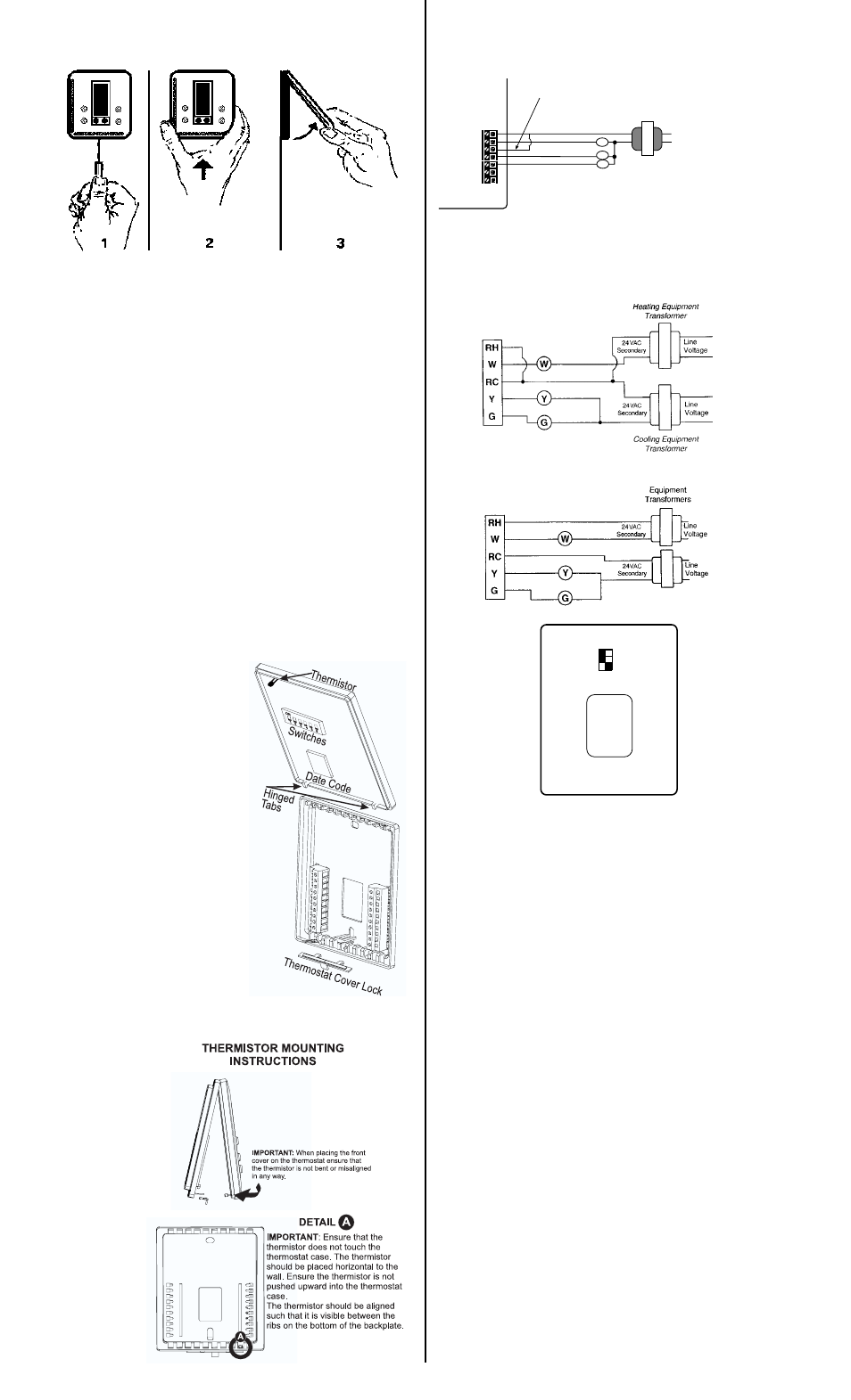
REMOVING THE THERMOSTAT FROM THE SUBBASE
1. Insert a flat blade screwdriver or coin 1/8" into the
slot located in the bottom center of the thermostat
case and twist 1/4 turn. When you feel or hear a click,
grasp the case from the bottom two corners and separate from
the subbase. Some models require more force than others
when separating due to the number of terminals used.
2. Swing the thermostat out from the bottom.
3. Lift the thermostat up and off the subbase.
4. Place the rectangular opening in the subbase over the equip-
ment control wires protruding from the wall and, using the sub-
base as a template, mark the location of the two mounting
holes (exact vertical mounting is necessary only for appear-
ance).
5. Use the supplied anchors and screws for mounting on drywall
or plaster; drill two 3/16" (5mm) diameter holes at the marked
locations; use a hammer to tap the nylon anchors in flush to
the wall surface and fasten subbase using the supplied screws.
(Do not over-tighten!)
6. Connect the wires from your system to the thermostat termi-
nals. Carefully dress the wires so that any excess is pushed
back into the wall cavity or junction box. Ensure that the wires
are flush to the plastic subbase. The access hole should be
sealed or stuffed to prevent drafts from the wall affecting the
thermostat.
7. Before the thermostat is reinstalled on the subbase, install the
optional clock/timer, indoor remote sensor and outdoor remote
sensor, if used. Refer to the installation instructions supplied
with each option. Also check the position of the DIP switches
on the back of the thermostat.
REPLACING THE THERMO-
STAT ON SUBBASE
1. Position the thermostat on the
hinged tabs at the top of the
subbase.
2. Gently swing the thermostat down
and press on the bottom
center until it snaps into place.
THERMOSTAT COVER LOCK
You may lock the cover down to pre-
vent unauthorized access to the
thermostat by adding the plastic
lock (included in the installation bag).
Insert the plastic lock piece into the
bottom of the mounted base. The
ends of the lock piece fit snugly
under the lock pins extending from
the bottom of the mounted base.
The tab in the middle of the lock
piece extends down from the base.
To release the locking mechanism,
press the lock piece up and into the
base while gently prying open.
THERMISTOR MOUNTING INSTRUCTIONS
When placing the front
cover on the thermo-
stat ensure the ther-
mistor is not bent or
misaligned.
Ensure that the ther-
mistor does not touch
the thermostat case.
The thermistor should
be placed horizontal to
the wall. Ensure the
thermistor is not
pushed upward
into the case.
The thermistor
should be aligned
so it is visible
between the ribs
on the bottom of
the subbase.
WIRING DIAGRAMS
SINGLE TRANSFORMER
TWO TRANSFORMERS
If the fault indicator is ON, the transformers are OUT OF PHASE.
Switch the secondary wires of one of the transformers (NOT
BOTH) and ensure the red light goes OFF.
Single RH/RC Wire
Separate RH and RC Wires
TERMINAL DESIGNATIONS
RH .............24 VAC from heating equipment transformer
W................Energizes the heating equipment with a call for heating
RC .............24 VAC from cooling equipment transformer
Y.................Energizes the cooling equipment with a call for cooling
G ................Energizes the fan circuit
CLK1 .........Independent remote clock/timer optional for
CLK2
alternate setpoints
RS2............Use to connect remote temperature sensor(s).
RS1
Refer to the instructions included
RS+V
with the sensors.
DIP SWITCH OPTIONS
Located on the back of the thermostat once the subbase is
removed.
Switch #1 – Allows for a 4-minute or 2-minute minimum on/off time.
Switch #2 – Allows for the keypad to be locked or unlocked.
Switch #3 – Allows for an immediate fan (electric heat) or a
natural delay for the fan (gas/oil heat).
SPECIFICATIONS
Rated Voltage
20-30 VAC, 24 nominal
Rated A.C.
0.08 Amps to 1.5 Amps continuous
Current
per output with surges to 4 Amps max.
Control
Heating: 38° to 88°F in 1° Steps
Range
5° to 30°C in 1° Steps
Cooling: 60° to 108°F in 1° Steps
16° to 40°C in 1° Steps
Thermostat
Measurement Range
28° to 124°F or 0° to 48°C
O.D.T. Displayed
Range
-50° to 124°F or -48° to 48°C
Control Accuracy
±0.5°C at 20°C, ±1°F at 68°F
Minimum
(between heating and cooling)
Deadband
2°F or 1°C
(Outside rear view with
backplate closed)
300-206
CLK1
CLK2
RS2
RS1
RS+V
Y
G
4 min. (on/off)
2 min. (on/off)
Unlocked
Locked
1
2
RC
3
Gas
Electric
RH
W
RH
W
RC
Y
G
CLK1
24 VAC
Transformer
Line
Voltage
G
Y
W
HEAT STAGE #1
FAN
CLK2
COOL STAGE #1
Add jumper for
single transformer