Installation instructions (cont), Wiring diagram terminal and switch designations, Clock terminals (option) clk1 – clk2 – Robertshaw 300-205 User Manual
Page 2: Remote sensor (option) rs1 – rs2 – rsv+1, Dip switch options, Specifications
INSTALLATION INSTRUCTIONS (CONT)
6. Connect the wires from your system to the thermostat termi-
nals. Carefully dress the wires so that any excess is pushed
back into the wall cavity or junction box. Ensure that the wires
are flush to the plastic subbase. The access hole should be
sealed or stuffed to prevent drafts from the wall affecting the
thermostat.
7. Before the thermostat is reinstalled on the subbase, install the
optional clock/timer, indoor remote sensor and outdoor remote
sensor, if used. Refer to the installation instructions supplied
with each option. Also check the position of the DIP switches
on the back of the thermostat.
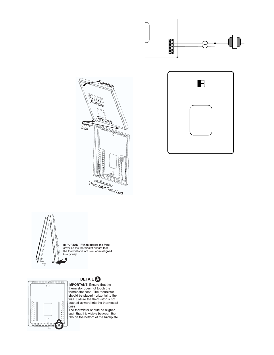
REPLACING THE THERMO-
STAT ON SUBBASE
1. Position the thermostat on the
hinged tabs at the top of the
subbase.
2. Gently swing the thermostat
down and press on the bottom
center until it snaps into place.
THERMOSTAT COVER LOCK
You may lock the cover down to
prevent unauthorized access to
the thermostat by adding the clear
plastic lock (included in the instal-
lation bag.) Insert the plastic lock
piece into the bottom of the
mounted base. The ends of the
lock piece fit snugly under the
lock pins extending from the bot-
tom of the mounted base. The tab
in the middle of the lock piece
extends down from the base.
To release the locking mechanism,
press the lock piece up and into
the base while gently prying open.
THERMISTOR MOUNTING INSTRUCTIONS
Outside rear view with backplate closed
WIRING DIAGRAM
TERMINAL AND SWITCH DESIGNATIONS
RC .............24 VAC from equipment transformer
Y ................Energizes on a call for cooling
G ................Energizes the fan circuit
CLK1 .........Use with remote clock/timer for
CLK1
alternate setpoints
RS2............Use to connect remote temperature sensor(s).
RS1
Refer to the instructions included
RS+V
with the sensors.
CLOCK TERMINALS (OPTION) CLK1 – CLK2
This thermostat is equipped with remote clock terminals. By con-
necting a remote clock/timer the thermostat can be alternated
between the DAY/NIGHT setpoints automatically.
REMOTE SENSOR (OPTION) RS1 – RS2 – RSV+1
The thermostat is designed to accept the electronic remote sen-
sor (Uni-Line part #10-528), which will allow you to locate your
thermostat in an area away from view.
DIP SWITCH OPTIONS
Located on the back of the thermostat, once the subbase is
removed.
Switch #1 – Allows for a 4-minute or 2-minute minimum on/off time.
Switch #2 – Allows for the keypad to be locked or unlocked.
SPECIFICATIONS
Rated Voltage
20-30 VAC, 24 nominal
Rated Current
0.08 Amps to 1.5 Amps continuous per
output with surges to 4 Amps max.
Control
Cooling: 60° to 108°F in 1° Steps
Range
16° to 40°C in 1° Steps
Thermostat
Measurement Range
28° to 124°F or 0° to 48°C
O.D.T. Displayed
Range
-50° to 124°F or -48° to 48°C
Control Accuracy
±0.5°C at 20°C, ±1°F at 68°F
300-205
CLK1
CLK2
RS2
RS1
RS+V
Y
G
RC
4 min. (on/off)
2 min. (on/off)
Unlocked
Locked
1
2
Y
RC
G
CLK1
G
Y
CLK2
24 VAC
Transformer
Line
Voltage