Archive, Troubleshooting, Theor – Ransburg Aviator Power Supply Unit 75983-02 User Manual
Page 22
CP-97-01.1
1 9
1 9
1 9
1 9
1 9
AVIATOR Power Unit - Maintenance
TROUBLESHOOTING
TROUBLESHOOTING
TROUBLESHOOTING
TROUBLESHOOTING
TROUBLESHOOTING
No kV at the Applicator
No kV at the Applicator
No kV at the Applicator
No kV at the Applicator
No kV at the Applicator
(Easy Checks)
(Easy Checks)
(Easy Checks)
(Easy Checks)
(Easy Checks)
• Ensure air is on to the AVIATOR.
• Ensure the AVIATOR is properly grounded.
• Filter is plugged, replace element.
• Ensure 60 psig (4.1 bar) air is present with
the unit running.
• Ensure voltage adjust potentiometer is ad-
justed to full voltage.
• Ensure air motor to generator coupling is
properly secured to the shaft of each.
• Ensure cable is installed into applicator prop-
erly.
• Ensure a compatibly designed applicator is
being used with the AVIATOR (AVIATOR
requires specific applicator models, see
"Aviator/Applicator Capability" in the "Parts
Identification" section).
• Switch applicators to determine if the appli-
cator or the AVIATOR is the cause of the
problem.
• Ensure pressure gauge reads 40-45 psi.
No kV at the Applicator
No kV at the Applicator
No kV at the Applicator
No kV at the Applicator
No kV at the Applicator
(Complex Checks)
(Complex Checks)
(Complex Checks)
(Complex Checks)
(Complex Checks)
If the AVIATOR is not producing power but you
can audibly hear the unit running, perform the
tests listed below to determine the cause of the
problem. Reference the "Maintenance" section
for repair/removal information.
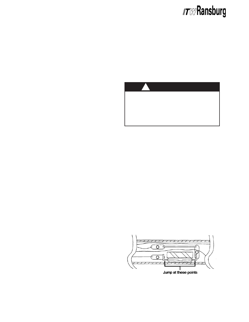
1. Remove the cable from the applicator by
loosening the cable set screw in the handle of the
applicator. Pull the sleeve back off the cable (see
Figure 5). Using a suitable jumper, jump around
the reed switch.
Using a suitable VOM meter and the AVIATOR
running, measure the voltage at the two (2) female
pin connections of the cable. If voltage exists, the
problem is either the air valve magnet (reference
appropriate applicator manual), the reed switch
itself, or the applicator. If the reed switch is bad, a
new plug assembly is required. Reference the
"Cable Removal" and "Cable Replacement"
sections of this manual.
Figure 5: Reed Switch Jump
Figure 5: Reed Switch Jump
Figure 5: Reed Switch Jump
Figure 5: Reed Switch Jump
Figure 5: Reed Switch Jump
THEOR
THEOR
THEOR
THEOR
THEORY
Y
Y
Y
Y OF OPERA
OF OPERA
OF OPERA
OF OPERA
OF OPERATION
TION
TION
TION
TION
The AVIATOR operates on standard clean, dry
air. The air is used to drive a rotating motor
(outside the gun) which is connected to a generator.
This generator puts out a voltage to the PC board
that converts the generator signal, conditions it,
and regulates it. This voltage is then transported
down the cable and halted at a reed switch at the
end of the cable. If the reed switch is open, the
applicator is off. If the reed switch is closed, the
applicator has been triggered and voltage is
produced by the applicator.
>
Prior to performing any maintenance on
the AVIATOR, all electrical circuits must be
de-energized. Be sure that the supply air is
completely disconnected from the unit and
the unit removed to a non-hazardous loca-
tion for service.
W A R N I N G
W A R N I N G
W A R N I N G
W A R N I N G
W A R N I N G
!!!!!
ARCHIVE