Archive, Air motor, Pc board remov – Ransburg Aviator Power Supply Unit 75983-02 User Manual
Page 20: Pc board remov pc board removal al al al al
CP-97-01.1
1 7
1 7
1 7
1 7
1 7
AVIATOR Power Unit - Maintenance
AIR MOTOR
AIR MOTOR
AIR MOTOR
AIR MOTOR
AIR MOTOR
REPLACEMENT/
REPLACEMENT/
REPLACEMENT/
REPLACEMENT/
REPLACEMENT/
INST
INST
INST
INST
INSTALLA
ALLA
ALLA
ALLA
ALLATION
TION
TION
TION
TION
The air motor used for this product has been
specifically designed for the application. Use of
any other part other than the ones purchased from
ITW Ransburg may not perform adequately or
may fail prematurely, and will also void all product
warranties.
1. Install the air motor air inlet fitting into the proper
port or the motor. The proper port is the port to the
right when the air motor shaft is pointing upward
and ports are facing forward.
2. Install the exhaust restrictor in the remaining
port.
3. Apply a light coat of dielectric grease (59972-
00) to the mounting shoulder of the air motor.
Locate one of the countersinks in the mounting
shoulder of the air motor. Align the countersink
with the threaded hole in the air motor mounting
plate. Push the air motor straight into the mounting
plate until the generator bottoms out. Tighten the
set screw.
4. Be sure the shaft of the air motor inserts directly
into the coupling. Tighten the coupling set screws
using a 5/64" Allen wrench.
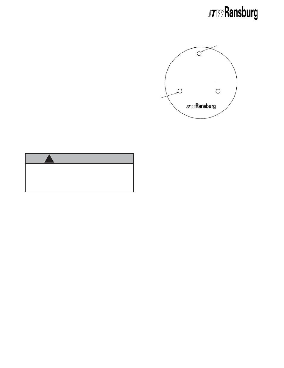
Figure 4: PC Board View
Figure 4: PC Board View
Figure 4: PC Board View
Figure 4: PC Board View
Figure 4: PC Board View
>
To extend the life of the air motor, do not
use any Teflon tape past the inlet to the filter
regulator unit. It is recommended to use a
liquid thread sealant such as 7969-10.
C A U T I O N
C A U T I O N
C A U T I O N
C A U T I O N
C A U T I O N
!!!!!
PC BOARD REMOV
PC BOARD REMOV
PC BOARD REMOV
PC BOARD REMOV
PC BOARD REMOVAL
AL
AL
AL
AL
1. Perform "Removal of Generating Unit from
Enclosure" procedure in the "Maintenance" section.
2. Perform "Generating Unit Disassembly"
procedure located in the "Maintenance" section.
3. Remove the explosion proof cylinder from the
upper plate by turning the cylinder counter-
clockwise.
4. Holding the upper plate assembly in your hand,
disconnect the PC board from the cable and at the
potentiometer connection. Both can be easily
removed by pressing the connector lever and
pulling straight apart.
5. Remove the PC board from the standoffs by
removing three (3) slotted screws. Be sure to
notice the position of the ground washer and the
standoff spacer.
Locate [41]
Locate [41]
Locate [41]
Locate [41]
Locate [41]
washer
washer
washer
washer
washer
here on
here on
here on
here on
here on
this side of
this side of
this side of
this side of
this side of
PC board.
PC board.
PC board.
PC board.
PC board.
Locate spacer [4]
Locate spacer [4]
Locate spacer [4]
Locate spacer [4]
Locate spacer [4]
at this location on
at this location on
at this location on
at this location on
at this location on
opposite side of
opposite side of
opposite side of
opposite side of
opposite side of
PC board.
PC board.
PC board.
PC board.
PC board.
ARCHIVE