Archive – Ransburg 9040 Classic HV Power Supply 76447 User Manual
Page 17
CP-97-02.5
9040 Classic for REA & M90 Systems - Installation
1 4
1 4
1 4
1 4
1 4
3. Using a small blade screwdriver, remove the
factory installed test jumper from 1TB-L1to 1TB-
L2.
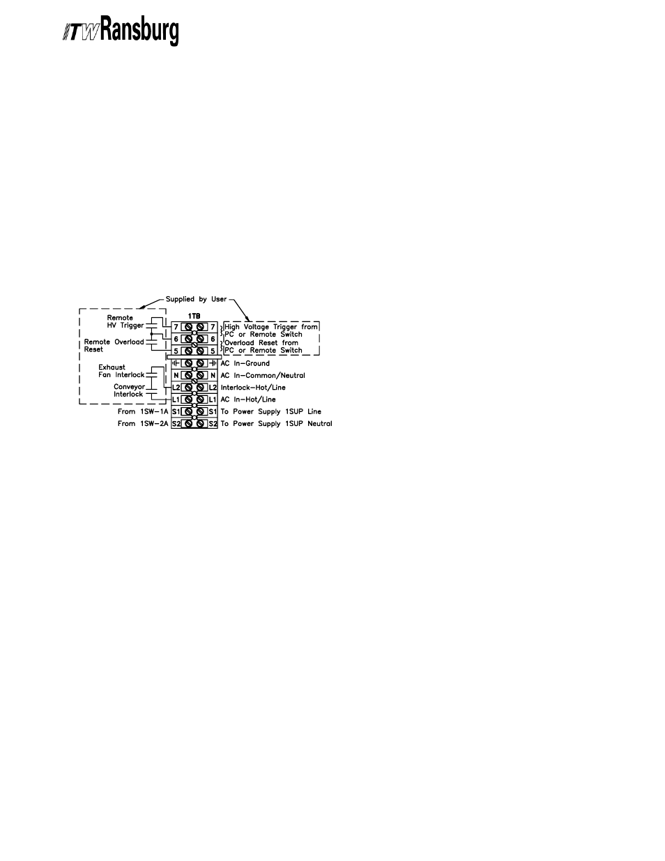
4. Route exhaust fan and conveyor interlock
(supplied by user) wiring through the external
wiring grommet on the side of the power supply
and connect to 1TB-L1 and 1TB-L2 as shown in
Figure 3. The interlock contacts should be
The interlock contacts should be
The interlock contacts should be
The interlock contacts should be
The interlock contacts should be
rated for at least 1 Amp at 240 volts AC.
rated for at least 1 Amp at 240 volts AC.
rated for at least 1 Amp at 240 volts AC.
rated for at least 1 Amp at 240 volts AC.
rated for at least 1 Amp at 240 volts AC.
5. Secure the cabinet door, replace the fuse and
plug the power supply in.
Figure 3: Terminal Block One (1TB)
Figure 3: Terminal Block One (1TB)
Figure 3: Terminal Block One (1TB)
Figure 3: Terminal Block One (1TB)
Figure 3: Terminal Block One (1TB)
External Relay Contacts
External Relay Contacts
External Relay Contacts
External Relay Contacts
External Relay Contacts
A set of external relay contacts for high voltage
(K1) and overload (K2) conditions is provided at
6PL-5, -6 & -7. See Figure 10 for exact wiring
locations. These relay contacts are sometimes
useful in configuring the control of the applicator
system.
Pneumatic Connections
Pneumatic Connections
Pneumatic Connections
Pneumatic Connections
Pneumatic Connections
(76447-10x, -12x, & -14x)
(76447-10x, -12x, & -14x)
(76447-10x, -12x, & -14x)
(76447-10x, -12x, & -14x)
(76447-10x, -12x, & -14x)
Connect the Air Filter Assembly (supplied) to the
IN port of the air flow switch on the side of the 9040
Classic power supply. Connect regulated (100
psi maximum) factory air to the other end of the Air
Filter Assembly. Be sure that the fittings remain
clean and are securely tightened. Attach the
applicator air line to the OUT port of the air flow
switch.
When the applicator is triggered, the resulting air
flow closes the contacts of the air flow switch,
thereby activating high voltage at the applicator.
Pneumatic Connections
Pneumatic Connections
Pneumatic Connections
Pneumatic Connections
Pneumatic Connections
(76447-13x)
(76447-13x)
(76447-13x)
(76447-13x)
(76447-13x)
Connect an atomization air pressure signal to one
pressure switch port and a trigger air pressure
signal to the other. When pressure signals (25 psi
minimum, 100 psi maximum) are applied to both
switches their contacts close, thereby activating
high voltage at the applicator. Both pressure
switches must be activated to receive high voltage.
External High V
External High V
External High V
External High V
External High Voltage Control
oltage Control
oltage Control
oltage Control
oltage Control
If a method of high voltage triggering, other than
the factory supplied method, is required, the 9040
Classic power supply allows for external high
voltage control from a PLC, pressure switch, air
flow switch, or other user supplied device. To turn
the high voltage on, the user supplied device must
create a contact closure between terminals 6 and
7 of terminal block one (1TB). To connect the user
supplied, external high voltage control device,
perform the following:
1. Ensure the front panel fuse is removed, the
power supply is unplugged, and the ON/OFF
switch is in the OFF position.
2. Open the power supply cabinet door.
3. Route the contact wires of the control device
through the external wiring grommet and connect
to the existing wiring for 1TB-6 and 1TB-7. The
The
The
The
The
control device contacts must be rated for at
control device contacts must be rated for at
control device contacts must be rated for at
control device contacts must be rated for at
control device contacts must be rated for at
least 100 millamps at 15 volts DC.
least 100 millamps at 15 volts DC.
least 100 millamps at 15 volts DC.
least 100 millamps at 15 volts DC.
least 100 millamps at 15 volts DC.
4. Secure the cabinet door, replace the fuse, and
plug in the power supply.
ARCHIVE