Operation, Ransburg, Operating instructions – Ransburg MCV2 Dual Purge Color Changer A10986-XX_A10993-XX User Manual
Page 16: Mcv 2 dual purge color changer - operation
OPERATION
OPERATING
INSTRUCTIONS
Each slice of the block contains 2 colors, one for
each side of the slice. There are two valves on
each side which are daisy chained internally. This
allows one inbound color line and one outbound
color line run from a paint supply to the dual
purge stack rather than two lines and two returns
for each color. This design uses half the tubing
normally needed for the dual purge applications.
However, there are two (2) 4mm ODT trigger lines
to open the valves to feed line A or line B.
The stack should be mounted as close to the
applicator as possible to minimize the waste ma-
terial left in the tube between the stack and the
applicator. An air push may be used to minimize
the material waste. However, this requires the
applicator to have a regulator on-board to control
the fluid pressure and flow to the applicator while
air is pushing. Both the Evolver and the RMA-202
have optional on-board fluid regulators available.
The normal function would be to have only one
trigger open at a time per side A or B. If more than
one trigger is opened per side, material contam-
ination will occur. The exception is the solvent
air chop that is required for cleaning the internal
porting of the stack.
An example is while Color 1 Trigger A is actuated
which would be supplying an applicator, side B is
being cleaned from the purge stack to the dump
of the applicator. Once cleaning is complete, any
color may be loaded into line B.
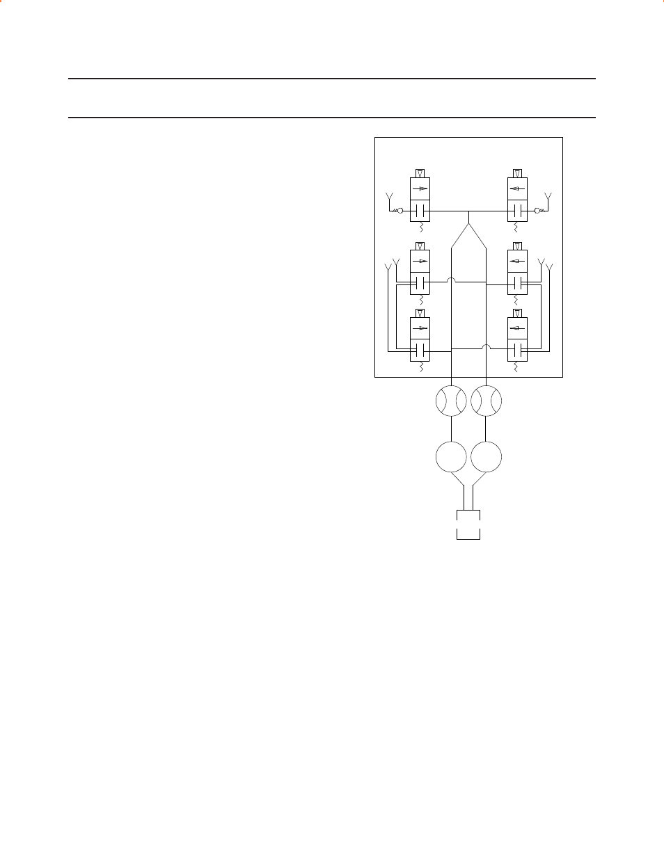
Figure 6 shows a typical Color Changer Schemat-
ics to prevent back flow of material.
Figure 6: Color Changer Schematics
FLOW METER
FLOW METER
LINE A
LINE B
FLUID REGULATOR
LINE A
FLUID REGULATOR
LINE B
COL
OR
2
O
U
T
COL
OR
2
IN
COL
OR
1
IN
COL
OR
1
O
U
T
SO
LV
ENT
MCV II DUAL PURGE
M
AI
N A
IR
SPRAY DEVICE
LINE A
SPRAY DEVICE
LINE B
SPRAY DEVICE
MCV 2 Dual Purge Color Changer - Operation
13
CS-05-01.9
Ransburg