Ransburg – Ransburg Serial Node Adapter LECU4002_78553 User Manual
Page 14
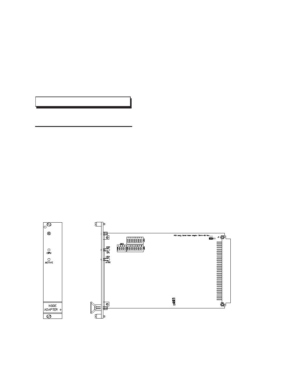
Figure 5: Printed Circuit Board
A 76111-XX I/O cable may be used to access the
pins in Figure 4.
The analog signal scaling may be either 0-10
Vdc or 4-20 mAdc as selected by switch SW3-3.
Digital inputs may be either 24 Vdc source (set
Jumper E2 in 2-3 position) or sink to ground (set
Jumper E2 in 1-2 position).
>
SW3 installed only in the Serial Node
Adapter + version.
NOTE
Serial Bus Connection To Other
Motherboards
The Serial Node Adapter/Serial Node Adapter +
communicates to other modules in the rack via the
local Serial Bus. If more than one motherboard
is communicating with the Serial Node Adapter/
Serial Node Adapter +, the Serial Bus must be
jumpered to motherboards not having a Serial
Node Adapter. This is done by a short section
of shielded twisted pair cable between connec-
tors labeled “Serial” or “CAN”, and being sure to
observe the (+) to (+) convention.
A bus termination resistor (120 ohms, 1/2w) must
be connected across the (+) and (-) terminals of
the final cable termination.
Serial Node Adapter/Serial
Node Adapter + Addressing/
Configuration
The Serial Node Adapter/Serial Node Adapter +
must be set for the appropriate RIO address. The
rack address and starting quarter are set by switch
SW1 as shown in Figure 6. The Operating Mode,
Last State, Baud Rate, and Rack Size are set by
positions 1-8 on switch SW2 as shown in Figure 6.
Serial Node Adapter/Serial Node Adapter + - Installation
Ransburg
10
LN-9238-02.3