Installation, Ransburg, Connections and configurations – Ransburg Serial Node Adapter LECU4002_78553 User Manual
Page 13
CONNECTIONS AND
CONFIGURATIONS
Input Power
Required input power is regulated 24 Vdc which
is supplied by the motherboard of the rack which
contains the Serial Node Adapter. An on-board
dc-dc converter makes 5 Vdc for the module's logic
level circuits. The Serial Node Adapter + may be
installed in any one of three motherboards. The
power connections for each are shown in Figure 2.
Remote I/O
The connection of the Allen-Bradley Remote
I/O (RIO) is made to the connector labeled RIO.
This connector is located at the top of each of the
above motherboards. The RIO cable wires are
connected as shown below.
The RIO cable may be "daisy-chained" from
one node to another per Allen-Bradley installa-
tion specifications. Where a termination resistor
is specified, usually the last termination point in
a chain, install the appropriate resistor directly
across ""BLU" and "CLR" on the RIO connector.
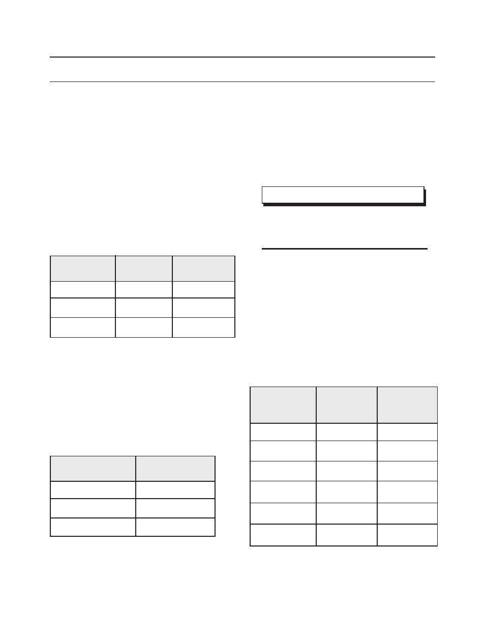
Figure 2: Input Power Connections
Motherboard
LECU4014-02
78145-00
78149-00
+24 Vdc
J10 - 1
J7 - 3 (+24)
J16 - 3 (+24)
24 Vdc com
J10 - 2
J7 - 4 (GND)
J16 - 4 (GND)
BLU
SHLD
CLR
RIO Wire
Blue
Bare
Clear
RIO
Terminal
Figure 3: RIO Cable Wire Connections
Remote I/O With Certain
Discrete Inputs (Serial Node
Adapter + Only)
Certain inputs may be controlled independent of
the Remote I/O communication in this mode set
by switch SW3, positions 1 and 2. (See Figure 6)
These inputs are KV Set and Speed Set (analogs)
and HV ON, Fluid Trigger and Di-dt inhibit (24V
digital). The pin connections for these signals are:
>
Switch SW3, positions 1 and 2 must
be in the OFF position for full RIO com-
munication.
NOTE
Figure 4: RIO Discrete Inputs
5A
4C
20C
17C
15C
18C
Inputs
KV Setpoint
Speed Setpoint
HV On
Fluid Trigger
Di/dt Inhibit
Spare
Pin
Connections
YEL
BRN
BLU/BLA
RED/BLA
ORG
----
76111-XX Ca-
ble Assy. Wire
Color
INSTALLATION
Serial Node Adapter/Serial Node Adapter + - Installation
Ransburg
9
LN-9238-02.3