Kv test jumper, Overload – Ransburg 9060 HV P.S. Air Motor 80102-31X User Manual
Page 24
9060 for No. 2 Process Handgun - Operation
19
CP-13-04.2
Figure 14: Jumper Location - Front Panel Lockout
Overload
The overload circuit may be activated for
applications that require overload indication or
notification of high current draws of the applica-
tor. The default overload value is set in the
software to the maximum microamp rating
minus 10 microamps.
1.
Turn AC power off and access the interior of
the Controller.
2.
Place the jumper across the two (2) pins at
location 17 on the main PC board (See
Figure 15).
3.
Close the Controller and turn AC power
back on. An overload fault will now occur if
the microamp display exceeds the overload
value.
Figure 15: Jumper Location - Overload Activation
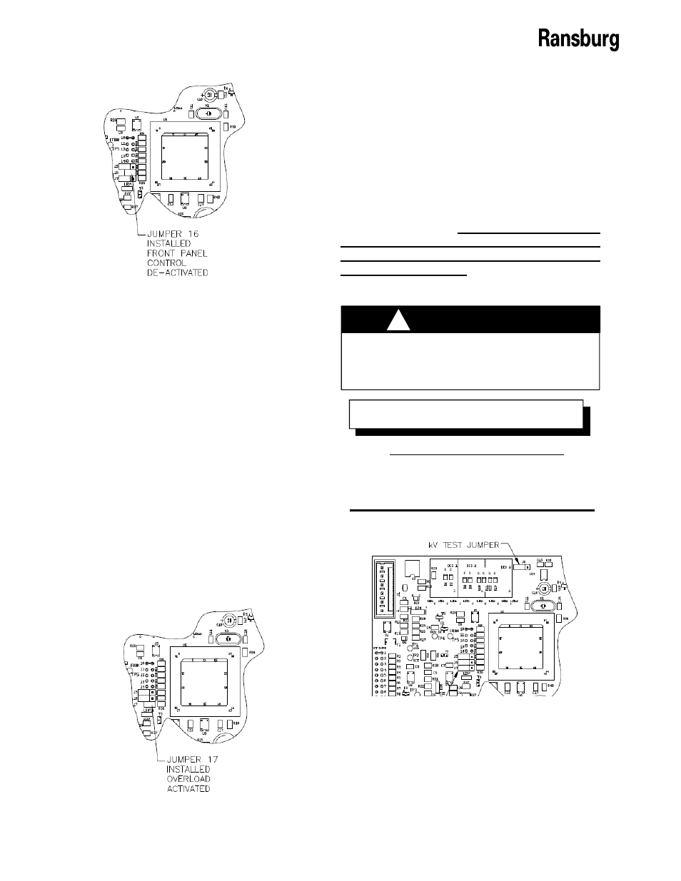
KV TEST JUMPER
To assist in testing and troubleshooting, a
jumper (J8) has been added to the main PC
board. By covering (shorting) both terminals of
this jumper, the high voltage of the spray
applicator can be activated. Thus, for testing
and troubleshooting, high voltage output can be
obtained without the need to trigger air through
the spray applicator. After testing, the jumper
must be repositioned so that it covers only
one terminal (open) or the high voltage will
stay on all the time.
See Figure 16 for the
location of KV test jumper J8.
If jumper J8 is left covering (shorting)
both terminals, high voltage will be on
whenever the AC power is turned on.
!
W A R N I N G
Use Ransburg Calibrated Equipment
ONLY
for testing and troubleshooting. Re-
fer to the “Accessories” section of this man-
ual for part numbers for testing equipment.
N O T E
Figure 16: Lockout Jumper Location