Operation, Start-up, Basic operations – Ransburg 9060 HV P.S. Air Motor 80102-31X User Manual
Page 22
9060 for No. 2 Process Handgun - Operation
17
CP-13-04.2
OPERATION
START-UP
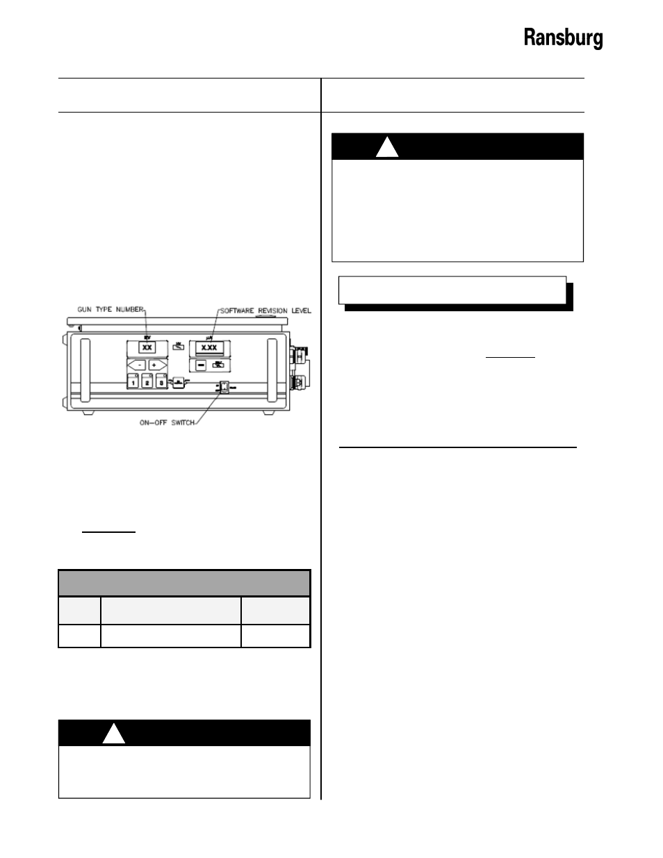
After all installation procedures are completed,
operation of the applicator may begin. When
the ON-OFF switch is turned on, the kV display
will show the applicator type the 9060 Controller
is configured for and the µA (microamp) display
will show the current software revision level as
shown in Figure 10. These items are displayed
for approximately 10 seconds.
Figure 10: Controller Start-Up Display
The controller comes preconfigured for the No.
2 Process Handgun (Air Motor) from the
factory. The following table lists the display
value and jumper setting for the unit. This table
is a reference to verify that the gun configura-
tion jumpers are in their correct positions if
unexpected behavior is observed.
USE ONLY the gun type configuration
for the No. 2 Process Handgun. Using
the wrong configuration may allow for op-
eration outside the recommended param-
eters and values for the applicator and
can result in damage or un-safe opera-
tion
.
!
W A R N I N G
After the initial start-up delay, the unit will be
configured for the applicator based on the gun
type jumper settings and is ready for standard
operation.
BASIC OPERATIONS
The basic operations are general operations
that are available.
Triggering
High voltage is actuated by the presence of an
active trigger signal. This is normally accom-
plished by pulling the trigger of the No. 2
Process Handgun to start the flow of air through
the applicator. The flow of air activates the air
flow switch which sends a trigger signal to the
9060 unit.
The kV setpoint is displayed on the kV display,
the actual current draw on the µA display, and
the high voltage light illuminates. Under the µA
display is a bar graph meter that illuminates
according to the actual current draw shown in
Figure 11.The green and yellow regions of the
bar graphs meter indicate output current is in
the optimum range for maximum transfer
efficiency. The red region of the bar graph
indicates high output current causing decreased
START-UP DISPLAY
Type Unit (Gun)
Jumpers
90
No. 2 Handgun (Air Motor)
10, 11
DO NOT adjust the gun configuration
jumpers. If they are incorrect, contact your
Ransburg representative.
!
W A R N I N G
During start-up, the gun trigger should
NOT
be pressed. An active trigger signal
will cause a non-resettable boot fault (bF)
and prevent the unit from being operated.
This is designed to prevent unintended fir-
ing of the high-voltage immediately after
start-up. Please refer to the “Fault Section”
of this manual for more information.
N O T E