Operator interface, Switches, Leds – Ransburg 9060 HV P.S. Air Motor 80102-31X User Manual
Page 15: Buttons
9060 for No. 2 Process Handgun - Introduction
CP-13-04.2
10
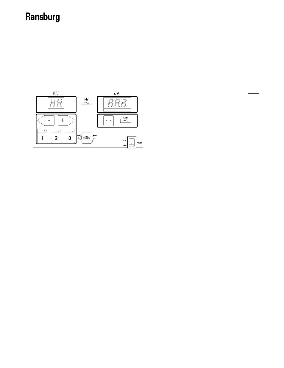
OPERATOR INTERFACE
The 9060 Controller shown in Figure 3, has a
simple operator interface consisting of 7 LEDs
(Light Emitting Diodes), one (1) power switch,
seven (7) buttons, one (1) current LED bar-
graph, and two (2) screens containing seven-
segment displays.
SWITCHES
Power Switch
The 9060 Controller contains a single rocker
switch for power On/Off selection. When the
unit is powered on, the screens should be lit
and display the gun display type information
and the software version number for a short
period of time.
LEDs
High Voltage On Indicator
The red High Voltage On Indicator is lit when a
trigger signal has been received by the unit and
the high voltage output from the cascade has
been enabled.
Fault Indicator
The red Fault Indicator is lit when a fault occurs
as determined by the microprocessor. When a
fault occurs the light will turn on and the identifi-
cation code for the fault will be displayed,
blinking, on the µA meter display. For more
information on the faults and fault ID codes,
please refer the Fault Descriptions section in
the Operations portion of this manual.
Figure 3: 9060 Operator Interface
LOCAL Mode LED Indicator
The LOCAL mode LED indicator is a left
pointing triangle and is located on the left side
the HV control button on the center of the
operator interface. This LED is lit when the
Controller is used with the No. 2 Process
Handgun.
Remote Mode LED Indicator
The remove mode LED indicator should NOT
be lit for No. 2 Process Handgun units.
Active Preset LED Indicators (3)
The active preset LED indicators are located
directly above each of the Preset Buttons.
When a preset button is pushed to select the
desired preset, in READY mode, the preset
LED indicator directly above the button pressed
will light up. Only one (1) preset light should be
lit at any one time.
BUTTONS
The seven buttons on the operator interface are
used to select the KV presets, reset overloads
and faults, access other modes and to navigate
as well as modify information that is displayed
on the two seven-segment display screens (µA
and kV).
Preset 1 Button
The Preset 1 Button (on the left below the kV
display) is used by itself to select “Voltage
Preset 1”. If pressed with the reset button, at
the same time, the screen will display the
resettable High Voltage ON operating hours for
3 seconds on the display screens.
Preset 2 Button
The Preset 2 Button (in the center below the kV
display) is used by itself to select “Voltage
Preset 2”. If pressed with the reset button, at
the same time, the screen will display the non-
resettable High Voltage ON operating hours for
3 seconds on the display screens.
Preset 3 Button
The Preset 3 Button (on the right below the kV
display) is used to select “Voltage Preset 3”.