No. 2 process hand- gun trigger signal – Ransburg 9060 HV P.S. Air Motor 80102-31X User Manual
Page 21
9060 for No. 2 Process Handgun - Installation
CP-13-04.2
16
NO. 2 PROCESS HAND-
GUN TRIGGER SIGNAL
The No. 2 Process Handgun uses a flow switch
(13742-02) to provide the trigger signal. The
listed flow switch is mounted inside the 9060
Controller chassis via the Air Flow Switch
Connector on the side panel. When the No. 2
Process Handgun trigger is pressed and flow
starts, the flow switch is activated and triggers
the high voltage.
For reference, when replacing a flow switch,
perform the following:
1.
Turn the 9060 Controller off, disconnect
it from its AC source, and remove the
fuses.
2. Open the controller cabinet door.
3. If the flow switch is being used, connect the
ground (green) lead from the flow switch to
the ground screw on the base plate shown
in Figure 8. The trigger signal (blue) lead
should be connected to the trigger signal
input on the JB-5 plug header that is
connected to the PC board.
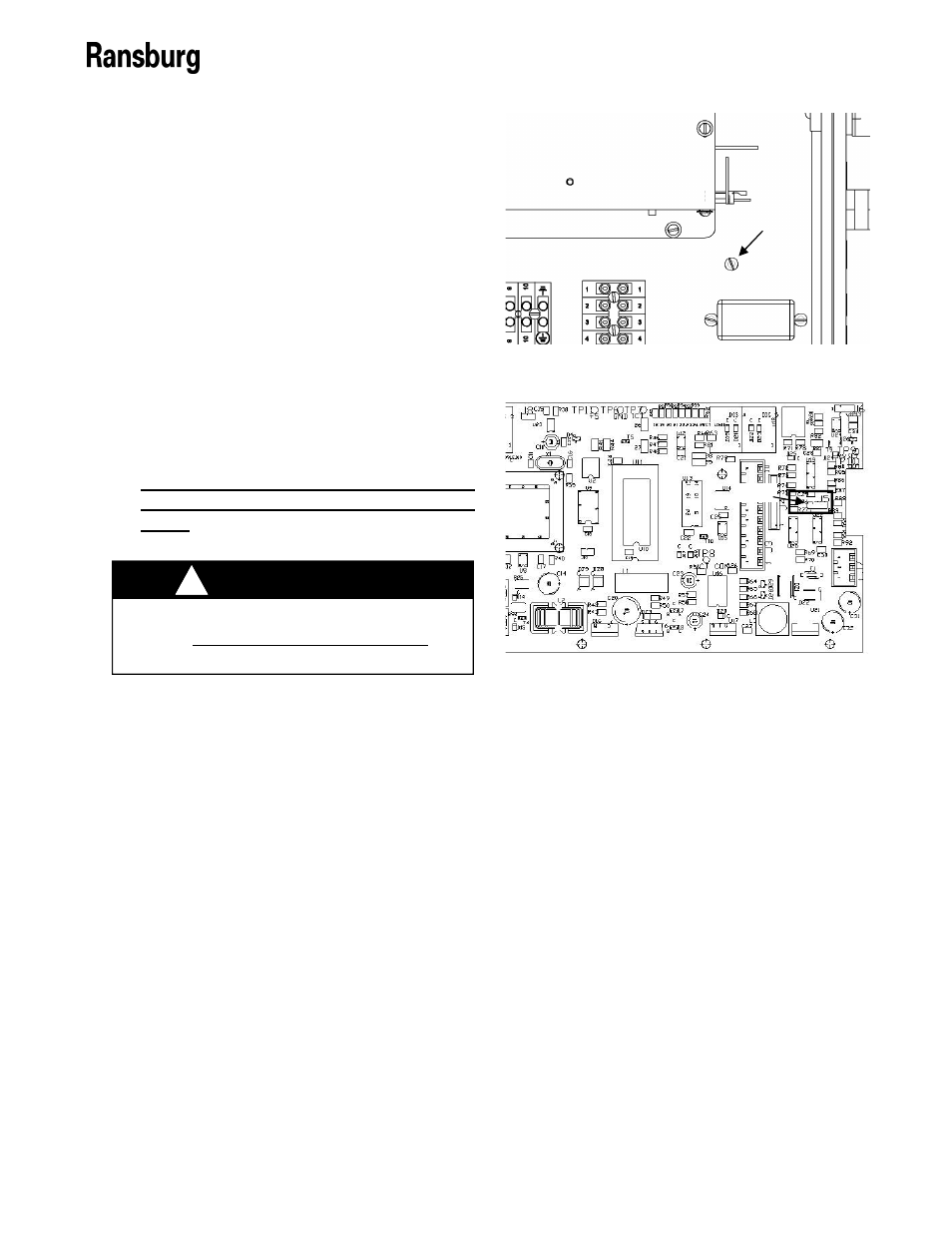
4. Verify that J5, shown in Figure 9, has the
shunt covering pins 1 and 2.
5. Secure the cabinet door, replace the fuses,
and reconnect the AC source.
ALWAYS double check that the Con-
troller is unplugged from its AC outlet
before working with any internal wiring.
!
W A R N I N G
Figure 8: Ground Screw on Base Plate
Ground Screw
Figure 9: PC Mainboard Jumper J5 Location
Pin 1