Connection interface, Connectors, Fuses – Ransburg 9060 HV P.S. Air Motor 80102-31X User Manual
Page 16
9060 for No. 2 Process Handgun - Introduction
11
CP-13-04.2
Left (-)/Right (+) Buttons
The left(-)/right(+) buttons are used to modify,
decrease and increase respectively, the cur-
rently selected preset value. If the button is
pressed and released, the preset value is
changed by 1 kV at a time. If the button is held
for over a 1/2 second, the value will begin
changing by 5 kV increments.
Reset Button
The reset button is used to clear fault or over-
load conditions. This will NOT prevent any
other active fault conditions from triggering a
new fault.
HV Control Button
This button, shown in the center of Figure 3, is
not functional for handgun units.
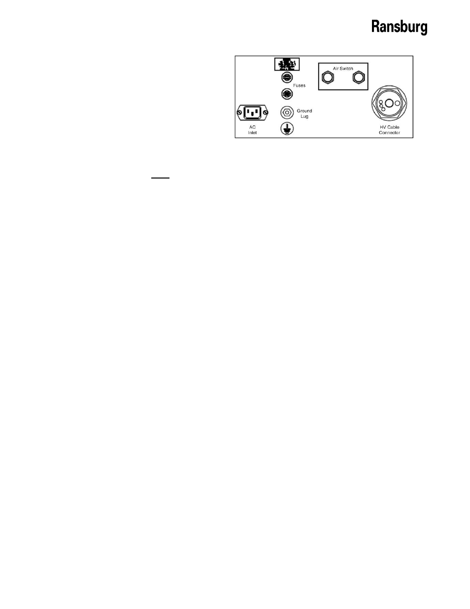
CONNECTION INTERFACE
The 9060 Controller connection interface shown
in Figure 4, provides all of the required connec-
tions for setting up a No. 2 Process Handgun
painting system. This connection interface
consists of one (1) high voltage cable connect-
or, one (1) ground lug connection, one (1) air
flow switch connection, two (2) fuses, and one
(1) AC inlet receptacle.
CONNECTORS
High Voltage Cable Connector
The high voltage cable connector is the largest
connector and is located on the far right of the
connection interface. This connector is de-
signed for use with the superflex high voltage
cable 20988 that connects with the No. 2
Process Handgun.
Ground Lug Connection
The ground lug connection is located directly
below the fuses and has a ground logo sticker
directly below it. This lug is provided as an
external ground connection point used to
ground the 9060 to an earth ground via a
ground cable. This ground lug connection can
also be used as the ground point for the high
voltage cable ground.
Air Flow Switch Connection
The air flow switch connection is installed to
provide a pneumatic trigger signal for the No. 2
Process Handgun indicating that the trigger has
been actuated. This signal is used to turn on
the High Voltage output.
AC Inlet Receptacle
The AC inlet receptacle is a standard IEC C14
Appliance Inlet connector with a maximum
rating of 250 VAC. It can handle both 110VAC
and 240 VAC inputs at 50 or 60 Hz. The unit is
shipped with the appropriate rated AC cord for
the particular installation.
FUSES
Fuses
There are two (2) time delay fuses (250V, 1A,
5mm x 20mm) installed in fuse holders on the
connection interface. They are located directly
above the ground lug connection. They are
present to provide a measure of safety against
power surges through the AC input. The top
fuse holder is connected in series between the
HOT line (L) input connection and the Interlock
AC line connection terminal 1TB-L2. The
bottom fuse holder is connected in series
between the neutral AC input connection and
the neutral input connection of the AC line
power filter.
Spare Fuses
The Controller also comes with two (2) spare
fuses (250V, 1A, 5mm x 20mm) mounted in
holders, inside the lid of the Controller.
Figure 4: 9060 Connection Interface