Kasco Marine 1400JFL User Manual
Page 4
4
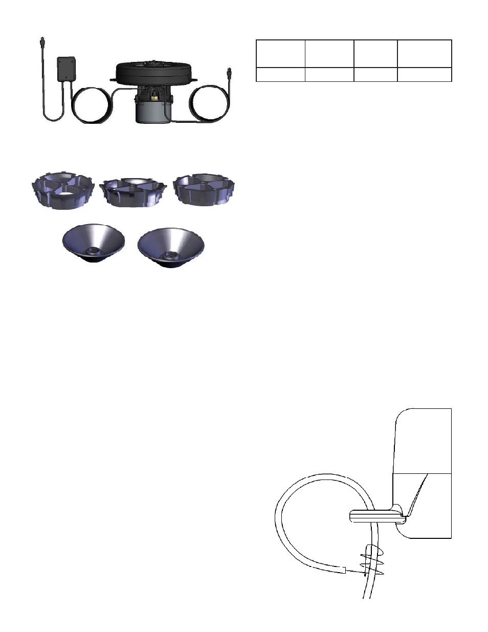
UNIT SPECS
Model
Voltage
Amps
Lock rotor
amps
1400JF
120 volts
3.1
10
Assembly & Installation
STEP ONE
Remove all contents from package and place
on a clean, fl at surface. Inspect the shipment
for any damages. If damages are found, im-
mediately notify your carrier and your Kasco
Marine, Inc. representative. Next, cross refer-
ence the parts included in the shipment with
the Parts Included sheet in this manual. Make
sure you have all the parts needed. If any
shortages are found, contact your Kasco repre-
sentative immediately.
STEP TWO
Locate and unwind the two braided nylon
ropes included with the shipment. There are
two molded Rope Holes on opposite sides of
the fl oat attached to the fountain assembly. Tie
one end of a rope to one rope hole with a se-
cure knot. Be sure not to leave too much of a
tail after the knot. Repeat with the other rope
on the other Rope Hole.
Interchangeable Nozzle Heads (Osprey
•
Installed) (5)
Osprey #1
Condor #2
Falcon #3
Eagle’s Nest #4
Hawk’s Nest #5
Braided 15’ Nylon Mooring Ropes (2)
•
1/4-20 x 7/8” Long Fillister head screw for
•
Nest patterns (1)
C-25, 120V Control Unit (1)
•
Nylon Cable Tie for securing cords and a
•
mooring rope (1)
TOOLS & SUPPLIES NEEDED
Anchors or stakes for installing unit (2)
•
Flat Head Screw Driver
•
Philips head screw driver for mounting
•
C-25 and Transformer (if lights are includ-
ed) and installing nozzles
120V Electrical Supply near pond on a
•
post with room for mounting the C-25 and
Transformer (if lights are included)
Two 12” pieces of 1” galvanized pipe for
•
weighting ropes (optional)
#6 x 3/4” long or longer screw for mount-
•
ing the Transformer (if lights are included)
(1)
#10 x 1” long or longer screw(s) for mount-
•
ing the C-25 (3)