Lock in amplifier theory of operation, Mathematical description of a lock in amplifier – Gentec-EO T-Rad (DB-15) User Manual
Page 9
T-RAD-DB15--USB Instruction Manual
Version 2.1
December. 2012
9
Data Displays
Real time, Strip chart, Tuning, Statistics
User input correction
factors
1 multiplier (transmission adjustment) (7 digits
floating point)
Positive External trigger
4.5 to 10 V @ 20 mA, optically isolated
External trigger pulse
width
80 ms
Analog-out
AC signal of the ADC input.
Internet Upgrades
Yes
PC Serial Commands
Yes
Dimensions
(connectors included)
147 (L) x 106 (W) x 34 (H) mm
Weight
0.424 kg
Power Over USB
Yes
T-RAD
1 Channel
1.2
Lock In Amplifier Theory of Operation
The operation of a Lock In Amplifier can seem mysterious given its ability to pull a useful signal
out of noise and interference, but the basics of operation are not complex. A lock in amplifier's
operation can be explained in three ways: mathematically, in the time domain, or in the frequency
domain. W hile all explanations are equally useful, the one that makes sense to the user is the
most useful, so a brief description of all three will be presented.
1.2.1
Mathematical Description of a Lock In Amplifier.
Fourier Theory tells us that all repetitive signals can be broken down into a series of sin
e’s and
cosines. Because of this fact, we can describe the lock in operation using a signal that is a pure
cosine wave. To go further, even if the input signal is not a pure cosine wave, the lock will extract
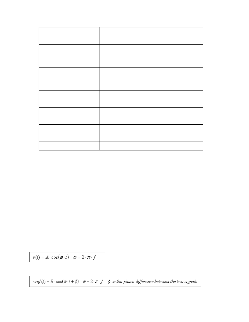
the pure cosine wave component of the signal anyway, so the approach is justified. Consider an
input signal, v (t), given by:
Now consider a second signal, the reference signal, given by:
This reference signal is at the same frequency as the input signal and is supplied by the lock in.