Gentec-EO M-LINK User Manual
Page 13
M-
LINK User’s Manual Revision 3.0
7
3-
Status LED:
The LED will turn on if the M-LINK is under power. The LED will flash if the head is not
connected.
4-
Analog-out:
The analog output of the M-LINK is the amplified signal from the detector head, that the ADC
sees. For power heads, the output = V
measured
/Current scale * 1.832 + V
off
Volts. It is
recommended to block off any optical power, make a zero offset and note the V
off
(V
off
is
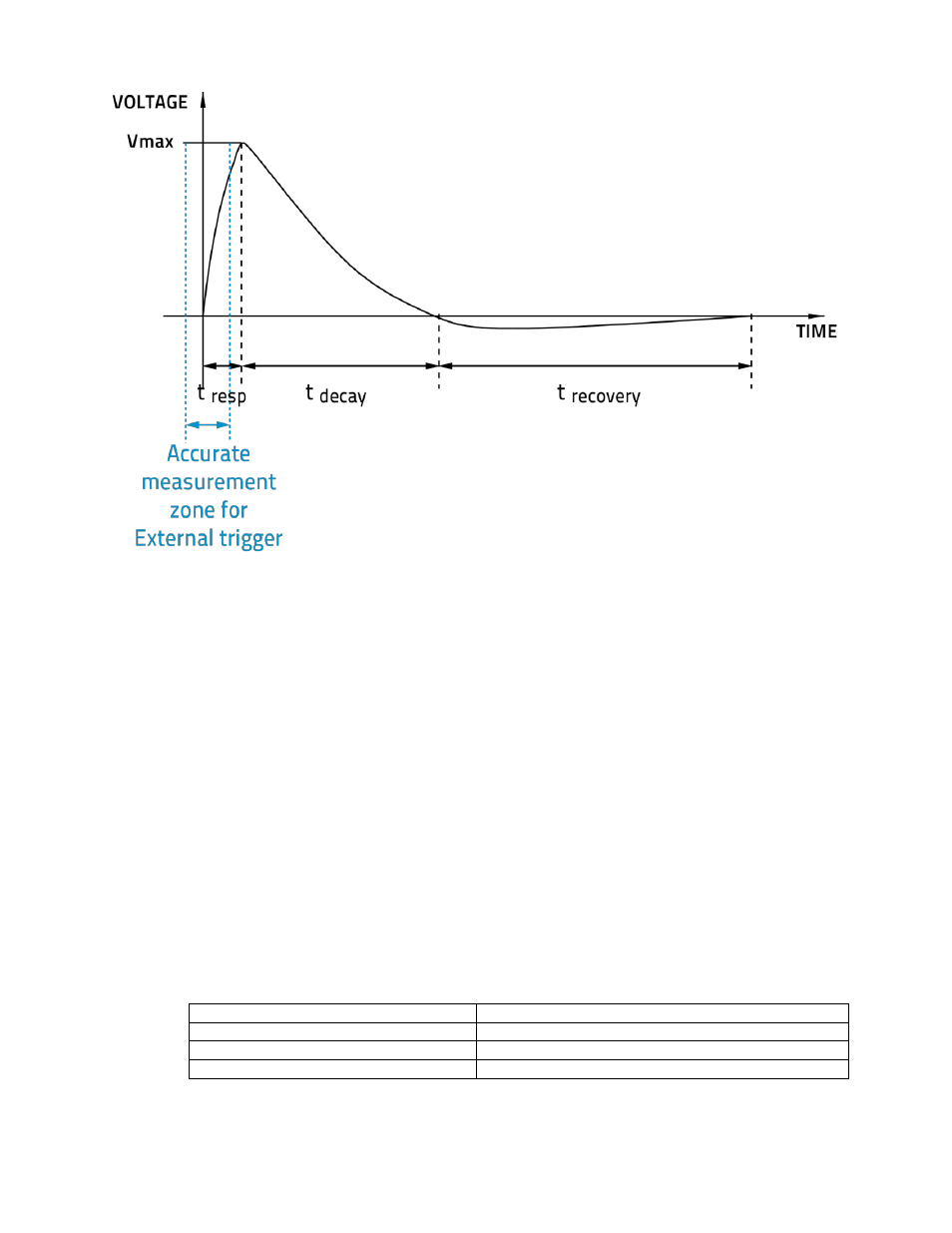
around 0.626V), it is not anticipated. For joulemeter heads, the output will follow the
joulemeter pulse, use an oscilloscope or an acquisition card to measure the signal. The
formula is (V
max
-V
min
)*1.832. V
max
is the maximum of the pulse. V
min
is the voltage just before
the pulse starts to rise.
5-
PROBE INPUT JACK:
The M-LINK uses a DB-15 female connector to mate with the detector heads (probes).
The M-LINK can take advantage of our Personal wavelength correction
™. It reads the
memory in the Smart Interface connector to provide a wavelength correction that is based on
spectral data measured from that specific detector.
Supported Heads version
Power Detector
≥5
Photodiode Detector
≥8
Energy detector
≥6
Active photodiode (PHXB and PEXB)
≥1