Onnector, Escriptions, M-link – Gentec-EO M-LINK User Manual
Page 11: Onnectors, Side, Db-15
M-
LINK User’s Manual Revision 3.0
5
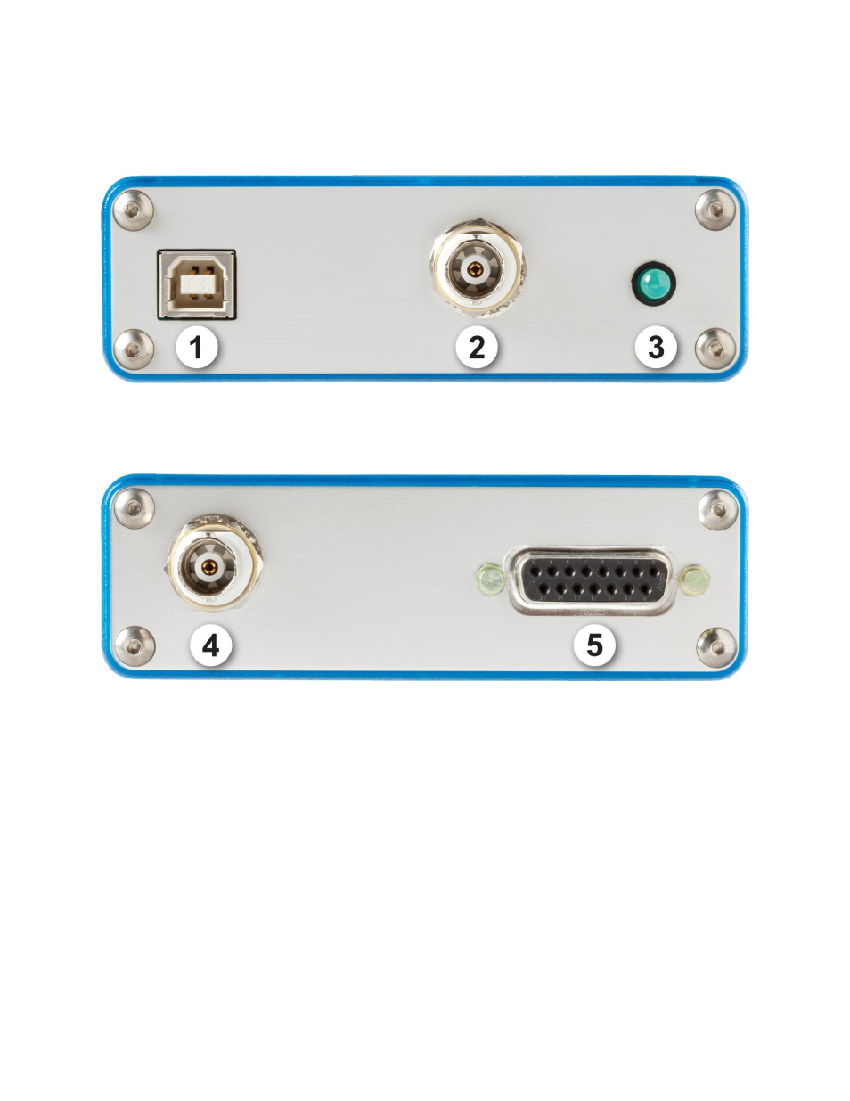
1.3 Connector Descriptions
Fig. 1-2 M-LINK Connectors (USB side)
Fig. 1-3 M-LINK Connectors (DB-15 side)
.
1-
USB INTERFACE CONNECTOR:
This interface allows remote control and data transfers between the M-LINK and a computer
that has a USB communication port.
2-
External trigger:
The Input connector is a Female BNC. The External trigger is TTL compatible. The monitor
detects a trigger on the rising or falling side of the external trigger signal. The polarity is user
selectable. To measure accurately, the trigger must be just before the laser pulse, or just after.