Teledyne 3220 - Multi-channel oxygen monitor system User Manual
Page 16
1 Introduction
Model 3220
Teledyne Analytical Instruments
2
1.2.1 System Chassis (19” Rack)
The System Chassis provides structural support and electrical
interconnection for the Control Unit and Channel Modules (up to eight
Channel Modules may be installed). The Channel Modules plug into the
sockets built into the System Chassis. Terminal strips at the rear of the
System Chassis provide for external electrical connections.
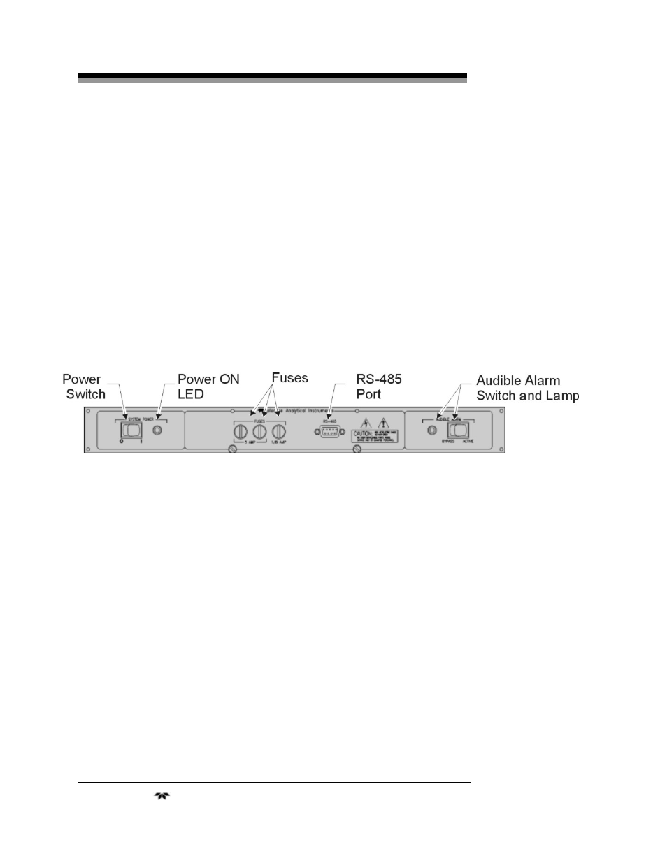
1.2.2 Control Unit
The Control Unit handles power distribution to the entire system. The
main power is controlled by a switch on the front panel and the system
fuses are accessible from the front. The Control Unit also contains common
alarm relays which indicate alarm conditions whenever any of the Channel
Modules alarm. The Control Unit is shown in Figure 1-2.
Figure 1-2: Control Unit
1.2.3 Channel Modules
Each Channel Module is a complete, self-contained instrument
including integral power supply and requires only external AC power
which it receives from the System Chassis socket. A channel is operational
when plugged into the System Chassis.
Because a Channel Module plugs into the Control Unit, channels can
easily be added to any control module with less than eight Channel
Modules even after installation to monitor additional locations. Channel
Modules in the same System Chassis may still be configured
independently. A Channel Module is shown in Figure 1-3.
1.2.3.1
M
AIN
F
EATURES OF THE
C
HANNEL
M
ODULE
The main features of the Channel Module include:
• High resolution LCD display readout
• Drop-in replacement for Model 322 instruments