Installation, Sizing air intake and exhaust piping – Fulton Caliber (CAL) Condensing Hydronic Boiler User Manual
Page 23
Questions? Please Contact Your Local Manufacturer’s Representative
SECTION 2
CAL-IOM-2014-0129
INSTALLATION
2-17
is used, the fi rst 8 inches (204 mm) must be CPVC material. Venting
installation must comply with National Fuel Gas Code, ANSI Z233.1, Part 10
or applicable provisions of local building codes.
2. Do not utilize automatic vent dampers or barometric dampers with the
Caliber boiler. Because the exhaust system operates at a positive pressure,
utilizing dampers could result in exhaust gases leaking into the boiler
room.
3. The exhaust line must be sloped down toward the boiler with a pitch of
at least 1/4” per foot. Failure to do so can result in a condensate pocket,
which can result in an inoperative boiler. There must be no low spots in the
exhaust pipe, as this can also result in a condensate pocket. A high spot is
acceptable, provided the pitch from the high spot is maintained back to
the boiler. Always avoid rigid connections between piping and structural
members of the building. The exhaust vent installer should be familiar
with Federal Codes as well as local codes and regulations.
4. Follow vent manufacturer’s instructions for installation of exhaust venting.
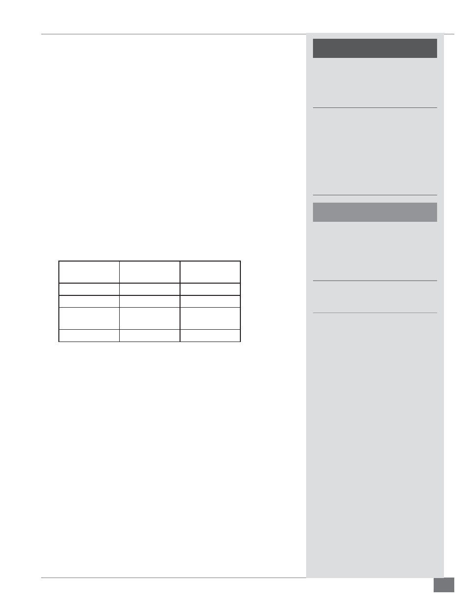
Refer to Table 5 for acceptable venting materials.
TABLE 5 - ACCEPTABLE VENTING MATERIALS
Venting
Material
Max. Flue
Temperature
Max. Water
Setpoint
PVC
200 F (93 C)
200 F (93 C)
CPVC
200 F (93 C)
200 F (93 C)
Polypropylene
(InnoFlue)
248 F (120 C)
200 F (93 C)
AL294C
550 F (287 C)
200 (93 C)
Note: Fulton accepts no liability for installation of any venting, including the selection of venting materials.
If PVC is used, the fi rst 8” must be CPVC. Do not use cellular/foam core pipe.
5. Stainless steel or galvanized steel pipe is recommended for all condensate
drain piping. Be aware that condensate drain piping can be as hot as the
exhaust stack on the boiler, and precautions should be taken to ensure this
pipe would not cause burns or other injuries to personnel that may be in
the boiler room.
6. Ensure that the condensate drain piping will not be exposed to
temperatures where water/condensate will freeze in the lines.
Sizing Air Intake and Exhaust Piping
CATEGORY II OR IV INSTALLATIONS, INDIVIDUAL PIPING FOR EACH BOILER:
The minimum fl ue stack length is 5 feet and the combined pressure drop of
the air intake and exhaust piping should not exceed 1.0”wc. This is typically the
equivalent of 70 ft and 8 elbows (combining the distances between the intake
and exhaust pipes). If a negative pressure is present in the stack during some
operating conditions, it should never be below -0.05”wc.
!
WARNING
Do not use the boiler as support for
ducted air piping. Ducted piping
must be supported independently of
the boiler.
Cements for plastic pipe are
fl ammable liquids and should
be kept away from all sources of
ignition. Proper ventilation should
be maintained to reduce the hazard
and to minimize breathing of cement
vapors. Avoid contact of cement with
skin and eyes.
4
CAUTION
Insulation should not be used on PVC,
CPVC, or polypropylene materials as it
may elevate pipe wall temperatures,
resulting in the potential for vent
material failure.
Appropriate cement must be used
when joining PVC to CPVC materials.