Ac connections – PROLiNK IPS5000 User Manual
Page 10
- 8 -
AC Connections
Installation should be done by a qualified electrician. Consult local code for the proper wire sizes,
connectors and conduit requirements.
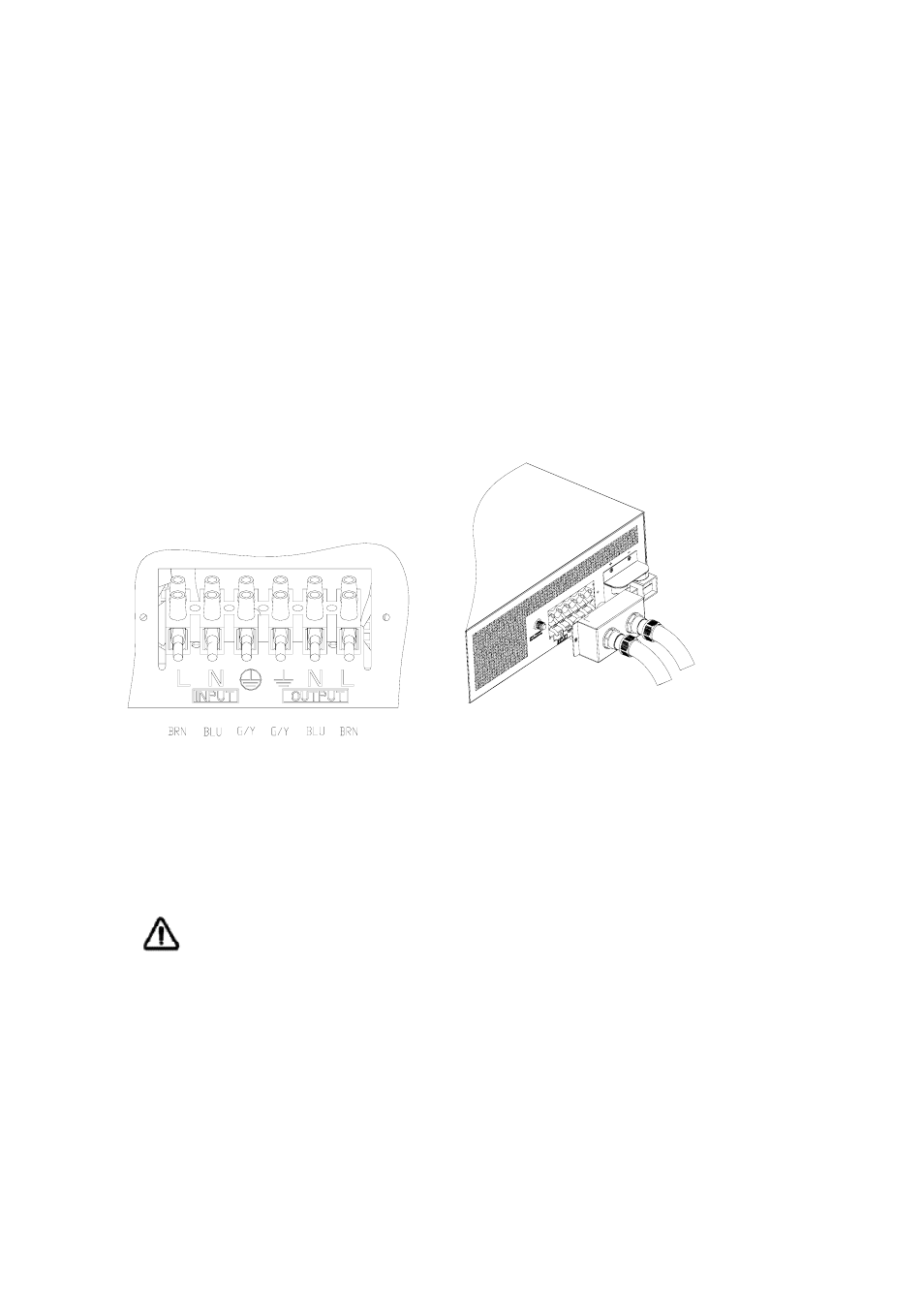
On the left of rear chassis is the AC hardwire cover. A six-station terminal block is provided to make
the AC connections. The terminal block is used to hardwire the AC input, AC output, and ground.
The National Electrical Code requires that an external disconnect switch be used in the AC input
wiring circuit. The AC breakers in a sub panel will meet this requirement.
Step 1- Disconnect the unit from the battery either by turning off the battery switch or removing the
battery cables from the battery. Turning off the unit does not constitute disconnecting from the
battery.
Step 2- Feed the wires through cable clamp and AC cover. See Figure 4.
Figure 4 AC Cable Connections to unit
Step 3- Following the wiring guide located in the AC wiring compartment as Figure 4, connect the
GND (green/yellow), Line (brown), and neutral (blue) wires from the AC input (utility, generator, etc)
to the terminal block.
Caution!! Be sure that AC source is disconnected before attempting to hardwire it to
the unit.
Step 4- Connect the AC Line output wiring to the terminal marked AC Line (output) following the
wiring guide inside the compartment. Connect the AC neutral out to the AC neutral out terminal.
Torque the wires into the terminal block.
Step 5- Use the two M3 screws to lock the AC cover.
Step 6-Tighten the clamps on the AC cable jackets (not the individual wires) to provide strain relief
for the connections.