Operation, Wid th in m m, 7 cm – PASCO OS-8529 SLIT ACCESSORY User Manual
Page 6: Laser beam optics bench diode laser
2
Slit Accessory
012–06348A
Operation
➀
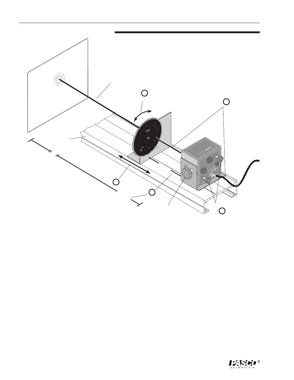
Place a slit set and the Diode Laser on the magnetic strips of the
optics bench about 7 cm apart. Position the optics bench so the
Diode Laser is about 1.5 m from a vertical, smooth white
projection surface such as a wall, cardboard, etc.
➁
Align the slit set and the Diode Laser on the optics bench by
abutting the edges of the brackets to the side railing of the optics
bench.
➂
Select the desired slit by rotating the disk until it clicks into place
with the slit at approximately the location of the laser beam on
the disk.
➃
Adjust the alignment of the laser beam with the slit by moving
the laser beam up-and-down and back-and-forth with the vertical
and horizontal adjustment screws until the diffraction pattern on
the projection surface is most intense.
➄
Slide the slit set back-and-forth slightly to find the position that
results in the most intense diffraction pattern.
ä Note: After the initial adjustment,
little or no additional adjustment to
the alignment of the laser beam
with the slit will be required when
you change the slit selection.
VA
RIA
BLE
VA
RIA
BLE
S
IN
G
L
E
S
L
IT
S
AP
ER
TU
R
E
S
P
A
T
T
E
R
N
S
VARIA
BLE
SL
IT
0.
4
m
m
0.2
m
m
a=
0.0
8
D
IA
0.
16
0
.0
8
0
.
0
4
0
.
0
2
a
=
:
H
O
LE
S
S
E
E
M
A
N
U
A
L
F
O
R
D
IM
E
N
S
IO
N
S
D
O
T
S
H
E
X
E
S
S
Q
U
A
R
E
S
a = 0.02
to
0.2
0
OPTICS SYSTEM
SLIT ACCESSORY
OS-8529
SINGLE SLIT SET
a
=
:
s
lit
w
id
th
in
m
m
LIN
E
DI
A
LIN
E/S
LIT
CI
R
C
U
L
A
R
646-06347-A
9 VDC 500mA
GND
3.5mm
HORIZONTAL
ADJUST
VERTICAL
ADJUST
ON
OFF
POWER
+9VDC
OS-8526
X-Y
ADJUSTABLE
DIODE LASER
2
4
5
1
3
~7 cm
~1.5 m
laser beam
optics bench
Diode Laser