PASCO PK-9023 EQUIPOTENTIAL AND FIELD MAPPER User Manual
Page 13
scientific
9
012-04346B
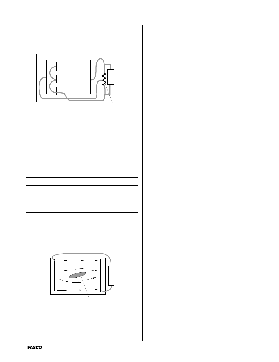
Triode
Equipment needed but not supplied: 5K Potentiometer
a
a
5K
Potentiometer
+
Use a 5 K potentiometer to provide three potentials. Con-
nect the three short electrodes with wires “a.” Do not let
these wires touch the black paper except at the conductive
ink electrodes.
Questions
How is the field in the area between the short electrodes
affected by the potential between the short electrodes and the
closer, long electrode?
Could this paper model of a triode act as an amplifying
device? If not, why not?
Fluid Mechanics Experiments
Cut-out shape
+
-
The PASCO Field Mapper can also be used to examine fluid
flow. In many fluid systems the velocity potential satisfies
the Laplace equations (so does the electromagnetic poten-
tial). Consequently, there is a direct analogy between fluid
flow and electric fields. In particular, the velocity potential
of an incompressible fluid where the flow is both steady and
not rotational satisfies the Laplace equation. A steady flow
of water is a good approximately of this type of flow. Now
the flow is generated by “sources” which supply fluid and
“sinks” which absorb fluid. We are interested in the
“streamlines” which can be thought of as lines traced out by
a particular particle in the fluid. The streamlines begin at the
sources and end at the sinks.
Turning to the Field Mapper, we need to draw electrodes in
the shape of the sources and sinks in the fluid flow to be
examined. Then the electric field lines which we plot
coincide with the streamlines in the fluid flow. (Remember
that the electric field lines are perpendicular to the equipo-
tential lines.) If there is some fixed obstruction in the fluid
glow, we can represent it by cutting the same shape from the
conductive paper. The schematic drawing shows a fluid
flow which is analogous to the flow in a section of pipe
(with frictionless walls). This source is a straight line at the
left, the sink is a straight line at the right. The tear-drop
shaped section cut out of the middle is some obstruction.
The field lines are the corresponding streamlines.
To use the Field Mapper to examine fluid flows, follow these
steps.
1.
Make sure that the fluid is incompressible and the flow
is not rotational and steady.
2.
Draw electrodes on the conductive paper in the same
shape and position as the sources and sinks in the flow.
3.
Cut out sections of the conductive paper in the same
shape and position as the obstructions in the fluid.
4.
Connect a battery between the sources and sinks. All
sources should be connected to the same side of the
battery. All sinks should be connected to the opposite
side.
5.
Plot the equipotentials and draw lines perpendicular to
these. You can also pick any point and determine the
direction of the maximum field gradient. This is the
direction of the streamlines at that point.