Introduction – PASCO TD-8561 THERMAL CONDUCTIVITY APPARATUS User Manual
Page 5
1
012-03349D
Thermal Conductivity Apparatus
Introduction
Thermal Conductivity Apparatus
Heat can be transferred from one point to another by three
common methods: conduction, convection and radiation.
Each method can be analyzed and each yields its own
specific mathematical relationship. The TD-8561 Thermal
Conductivity Apparatus allows one to investigate the rate
of thermal conduction through five common materials
used in building construction.
The equation giving the amount of heat conducted through
a material is:
∆
Q = k A
∆
T
∆
t / h.
In this equation,
∆
Q is the total heat energy conducted, A
is the area through which conduction takes place,
∆
T is the
temperature difference between the sides of the material,
∆
t is the time during which the conduction occurred and h
is the thickness of the material. The remaining term, k, is
the thermal conductivity of a given material.
The units for k depend upon the units used to measure the
other quantities involved. Some sample conversions
between different possible sets of units are shown in Table
1.
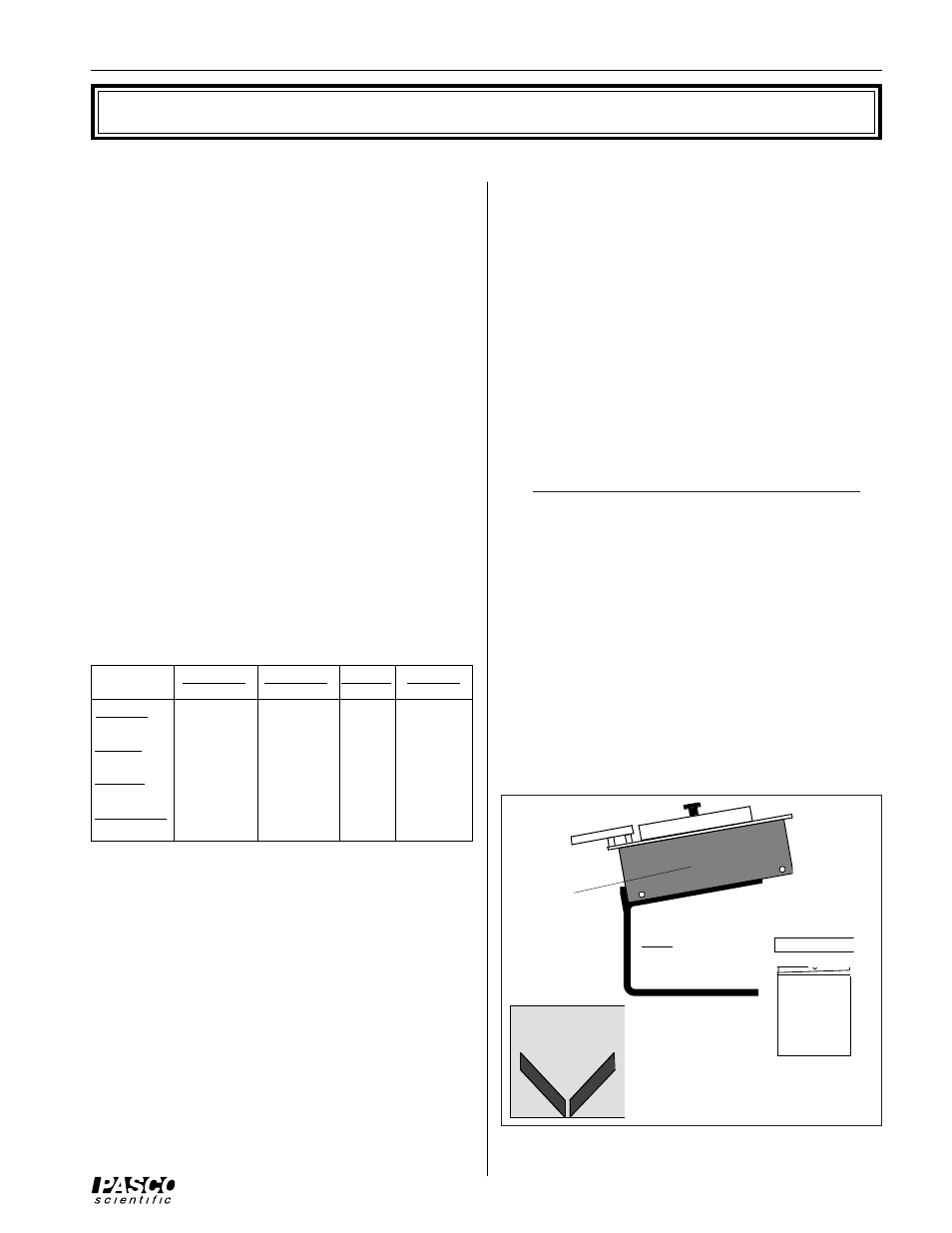
Figure 1 Equipment Included with the Thermal
Conductivity Apparatus
The importance of k lies in whether one wishes to conduct
heat well (good conductor) or poorly (good insulator).
Therefore, the relative size of k is of importance to
designers and builders, and should be of importance to
home owners.
Note further that choosing a material with a small value
for k does not guarantee a well-insulated structure. The
amount of heat conducted out in winter (and therefore
needing to be replaced) depends also upon three other
factors: area, thickness and temperature difference. The
same holds true for heat conducted in during the summer.
The equation for determining k is:
k =
∆
Q h / A
∆
T
∆
t = _____
Btu in.
Btu in.
Btu ft
Btu in.
in.
2
sec
°
R
in.
2
hr
°
R
ft
2
hr
°
R
ft
2
hr
°
R
Watt cm
1.338 x 10
-2
4.818
57.82
693
.
8
cm
2
°
K
Watt m
1.338 x 10
-5
4.818 x 10
-2
0.5782
6.938
m
2
°
K
Watt in.
9.485 x 10
-4
3.414
40.97
491.7
in.
2
°
R
Cal cm
5.600 x 10
-3
20.16
241.9 2.903 x 10
3
cm
2
sec
°
K
Table 1
Materials to test
(Glass, wood,
lexan, masonite,
sheet rock)
Base
Steam
chamber
with hardware
for
mounting
sample
Ice mold
(Part# 648-03427)
The technique for measuring thermal conductivity is
straightforward. A slab of the material to be tested is
clamped between a steam chamber, which maintains a
constant temperature of 100
°
C, and a block of ice, which
maintains a constant temperature of 0
°
C. A fixed tempera-
ture differential of 100
°
C is thereby established between
the surfaces of the material. The heat transferred is
measured by collecting the water from the melting ice. The
ice melts at a rate of 1 gram per 80 calories of heat flow
(the latent heat of melting for ice).
The thermal conductivity, k, is therefore measured using
the following equation:
k = (cal cm/cm
2
sec) =
(mass of melted ice) (80 cal/gm) (thickness of material)
(area of ice) (time during which ice melted) (temp.
differential)
where distances are measured in centimeters, masses in
grams, and time in seconds.
The Thermal Conductivity Apparatus includes the follow-
ing equipment (see Figure 1):
• Base
• Steam chamber with hardware for mounting sample
• Ice mold with cover (Part # 648-03427)
• Materials to test: Glass, wood, lexan, masonite, and
sheet rock (The wood, masonite, and sheet rock are
covered with aluminum foil for waterproofing.)