PASCO ME-6617 ROCKET ENGINE TEST BRACKET User Manual
Page 4
Rocket Engine Test Bracket
012-06418A
4
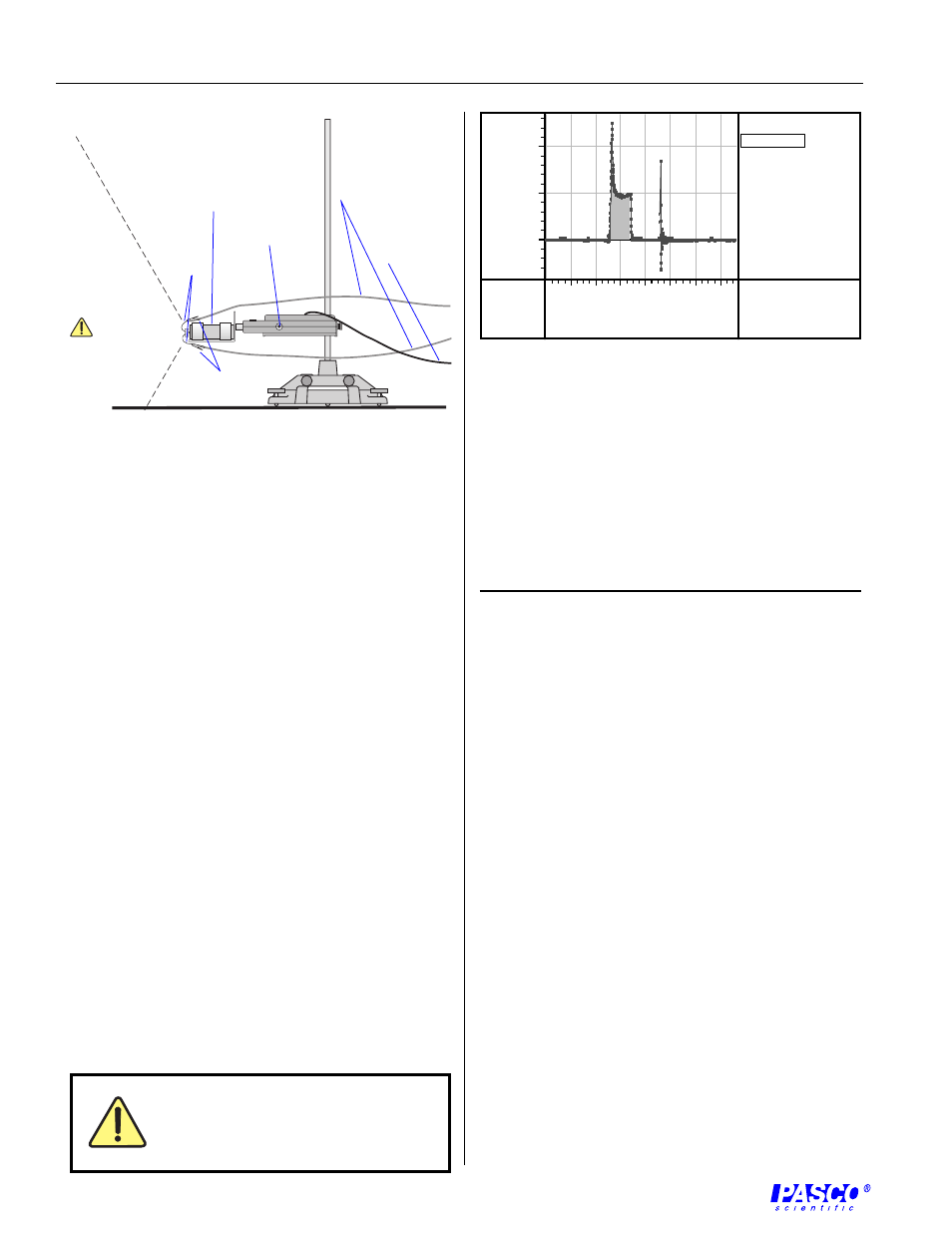
Figure 5
Graph of typical experimental results of a test of an Estes
C6-3 model rocket engine
Limited Warranty
PASCO scientific warrants the product to be free from
defects in materials and workmanship for a period of one
year from the date of shipment to the customer. PASCO
will repair or replace, at its option, any part of the product
which is deemed to be defective in material or
workmanship. The warranty does not cover damage to
the product caused by abuse or improper use.
Determination of whether a product failure is the result of
a manufacturing defect or improper use by the customer
shall be made solely by PASCO scientific. Responsibility
for the return of equipment for warranty repair belongs to
the customer. Equipment must be properly packed to
prevent damage and shipped postage or freight prepaid.
(Damage caused by improper packing of the equipment
for return shipment will not be covered by the warranty.)
Shipping costs for returning the equipment after repair will
be paid by PASCO scientific.
Address:
PASCO scientific
10101 Foothills Blvd.
P.O. Box 619011
Roseville, CA 95678-9011
Phone:
(916) 786-3800
FAX:
(916) 786-8905
email:
web:
www.pasco.com
Calculate the expected height of a rocket propelled with
an identical rocket engine from the force and mass data,
and compare with the actual height attained in a flight test.
Suggested Activity
5.
Press the TARE button on the Force Sensor (Figure 4).
➤
Note:
For the 500 interface in remote mode,
press the TARE button after the log button has
been pressed and the LED has flashed 10 times.
6.
Check the exhaust area to ensure it is clear of any
combustible material, people, or animals.
Data Collection
1.
Insert the safety key into the launch controller.
2.
Begin recording data and move to 15 feet (5 meters)
away from the Rocket Engine Test Bracket.
3.
Ignite the rocket.
4.
After the burn, stop recording data.
Data Analysis
1.
In Science Workshop, click the statistics button and
select Integration from the pop-up menu, and click
the Autoscale button to resize the graph.
2.
Select the area under the curve and record the
integrated value (impulse of the rocket engine).
3.
Use the smart cursor to determine the time to the
ejection charge.
4.
Compare your recorded values with the expected
values for the type of you are using.
The exclamation point within an
equilateral triangle is intended to alert the
user of important operating and safety
instructions that will help prevent damage
to the equipment or injury to the user.
T
A R E
Keep
exhaust
area clear!
to electronic
launch controller
Figure 4
Completed experimental setup
to computer
interface
igniter
wires
cable clips
model
rocket
engine
Force
Sensor’s
TARE
button
Time (s)
0
2
4
6
8
10
12
14
Integration
area = 8.51336 N s
0
5
10
R
un #1
F
o
rce
(N
)