PASCO ME-6617 ROCKET ENGINE TEST BRACKET User Manual
Page 3
012-06418A
Rocket Engine Test Bracket
3
T
AR
E
Setup
Set up the equipment
1.
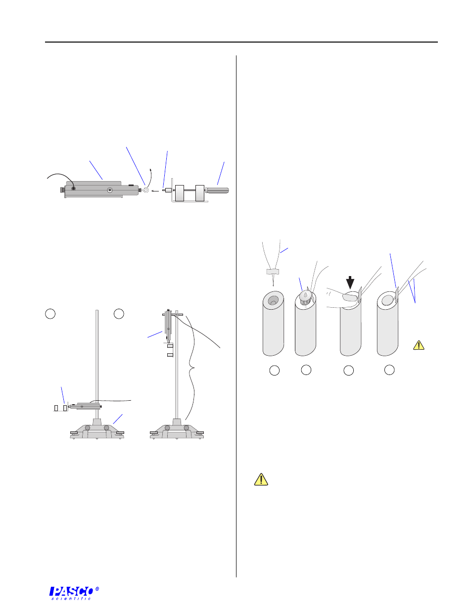
Remove the hook from the end of the Force Sensor.
Use a small screwdriver to connect the Rocket
Engine Test Bracket to the Force Sensor in place of
the hook (Figure 1).
2.
Mount the Force Sensor on the support rod in one of
two ways: horizontally (Figure 2a) or vertically
(Figure 2b).
3.
Insert the model rocket engine into the test stand
with the engines exhaust port pointing away from
the Force Sensor.
Set up Science Workshop
1.
Set up the Force Sensor in Science Workshop on ana-
log channel A.
2.
Adjust the sampling rate for the Force Sensor to 500
Hz.
➤
Note: Refer to the Users Guide to Science
Workshop (Sampling Options) for details on
adjusting the sampling rate.
3.
Open a Graph display.
➤
Note:
If you are using a 500 computer interface,
prepare it for remote data logging (refer to the
Users Guide to Science Workshop (Remote Data
Measurement with the Science Workshop 500
Interface).
Prepare for Ignition
1.
Move the equipment to the launch site.
2.
Insert the igniter into the rocket engine and spread the
wires apart, leaving the paper separator in place
(Figure 3).
➤
Note:
Carefully follow the instructions that
accompany the rocket engine and igniter.
3.
Clip the alligator clips of the cables from the launch
controller to the igniter wires.
Note: Do not allow the igniter wires or
alligator clips to touch each other. Be certain that
the safety key is not in the launch controller.
Insure that the cables are well away from the
exhaust area (Figure 4) and the computer
interface is as far away from the exhaust area as
possible.
4.
Plug the Force Sensors DIN connector into analog chan-
nel A.
Figure 1
Attaching the Rocket Engine Test Bracket to the Force
Sensor
Remove hook.
screwdriver
Force Sensor
Screw into
threaded
connector.
T
A R E
a
Figure 2
a) horizontal mount b) vertical mount
Figure 3
Inserting the igniter into the model rocket engine
Wires
must not
touch each
other!
igniter
plug
igniter
tape separator
a
b
c
d
at least
80 cm
T A
R
E
b
Rocket
Engine Test
Bracket
Force
Sensor
rod stand