PASCO ME-8598 Venturi Apparatus User Manual
Page 12
®
V e n t u r i A p p a r a t u s
0 1 2 -0 9 4 8 6B A p p e n d i x B : F l u i d S u p p l y a n d F l o w R a t e
12
1.
Install the three-step pulley on the rotary motion sensor.
2.
Clamp the rotary motion sensor above the reservoir (see Figure 10).
3.
Tie the float to one end of the string and the weight to the other end. Place the
float in the reservoir, run the string over the large step of the pulley, and let the
weight hang freely. Ensure that the weight will be free to move up as the water
drains.
4.
In DataStudio (or on the GLX) enable the Linear Velocity measurement of the
rotary motion sensor and set the Linear Scale value to Large Pulley.
5.
Create a flow-rate calculation: In the DataStudio Calculator window (or GLX
Calculator screen) enter the following definition:
R = v * A
Define the variable v as the velocity measurement. Define A as a constant equal
to the horizontal cross-sectional area of the inside of the reservoir. Measure the
area in units of m
2
. In this way, R is calculated in units of m
3
/s.
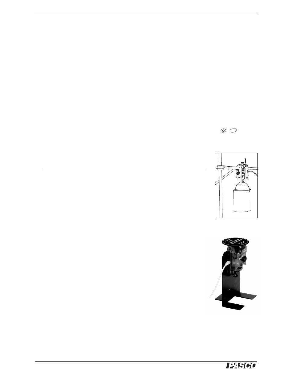
Water-flow Measurement Method 3: Force Sensor
In this method, a force sensor measures the increasing weight of the water in the catch basin.
1.
Clamp the force sensor under the lab bench with the hook pointed down and hang
the container from the sensor’s hook (see Figure 11).
or
Setup the force sensor on the floor with the Balance Stand and Pan and place the
container on the pan.
2.
Position and secure the end of the outflow tubing so it will drain water into the
container but not interfere with the weight measurement.
3.
Create a flow-rate calculation: In the DataStudio Calculator window enter the
following definition:
R = -derivative(2,F)/(9.81*1000)
Define the variable F as the Force (push positive) measurement. In this way, R is
calculated in units of m
3
/s.
The calculator definition above can be express in standard notation as
Other Parts Required or Recommended
Part Number
Force Sensor
PS-2104
Equipment for mounting sensor:
Multi clamp
SE-9492
Mounting rod
SA-9242
or Force Sensor Balance Stand and Pan
CI-6460
Container for catching water (with a handle if it is to be hung
from the force sensor)
3
In DataStudio, click the
Setup button to open the
Experiment Setup win-
dow. Enable Linear
Velocity under the Mea-
surements tab. Set the
Linear Scale under the
Rotary Motion Sensor
tab.
On the GLX (in stand-
alone mode), go to the
Setting Screen by press-
ing +
.
F4
Force sensor
Outflow
tubing
Container
Figure 11: Force
sensor and container
Figure 12: Balance
Stand and Pan
4
If you are using a GLX
in standalone mode, cal-
culate
R manually after
data collection using the
slope of the force versus
time graph.