Part i: spring constant procedure, Data analysis – PASCO ME-9429B 1.2 m Classic Dynamics System User Manual
Page 30
®
1 . 2 m C l a s s i c D y n a m i c s S y s t e m
E x p e r i m e n t 9 : C o n s e r v a t i o n o f E n e r g y
30
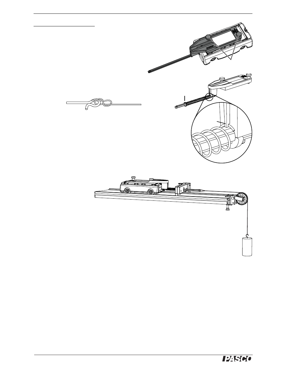
Part I: Spring Constant
Procedure
1.
Fit the spring cart launcher onto the top of the cart (as illustrated).
Tighten the thumbscrews to secure it.
2.
Select
one of the included springs. Slide it onto
the launcher shaft with the flared end out. Turn the
spring to secure the end in the spring retention hole as illustrated.
3.
Tie the string to the release pin.
4.
Install an end stop about 20 cm from the end of the track.
5.
Clamp a pulley to the same end of the track.
6.
Position the track so that a mass hanging from the pulley is free
to hang over the edge of your lab bench.
7.
Level the track so that the cart does not roll when release
d from a
standstill.
8.
Place the cart on the
track with the
launcher shaft
through the hole in
the end stop.
9.
Tie a piece of string (about 40 cm long) to the launcher shaft. Run the string over
the pulley and hang a 100 g mass from the string.
10. Adjust the pulley so that the string is horizontal between the pulley and the
launcher shaft.
11. In a table, record the position of the cart on the track and the total mass hanging
from the string.
12. Add 100 g to the hanging mass.
13. Repeat steps 11 and 12 up to about 500 g.
Data Analysis
1.
Calculate the force applied to the spring at each step: F
x
= m
h
g, where m
h
is the
hanging mass and g = 9.8 m/s
2
.
2.
Make a graph of F
x
versus cart position.
3.
Draw a best-fit line on your graph. The slope of that line equals the spring con-
stant, k.
Untie the string from the launcher shaft and remove the pulley for the next part.
Release pin
String
Thumbscrews
Flared
end
Spring
retention
hole