Setup, Where m, Is the mass of the ball, v – PASCO ME-6815 PROJECTILE CATCHER ACCESSORY User Manual
Page 16: Is the muzzle velocity of the ball, m
Projectile Catcher Accessory
012-05091E
12
where m
b
is the mass of the ball, v
o
is the muzzle velocity of the ball, m
c
is the mass of
the catcher and cart, and v is the velocity of the cart and ball immediately after the
collision.
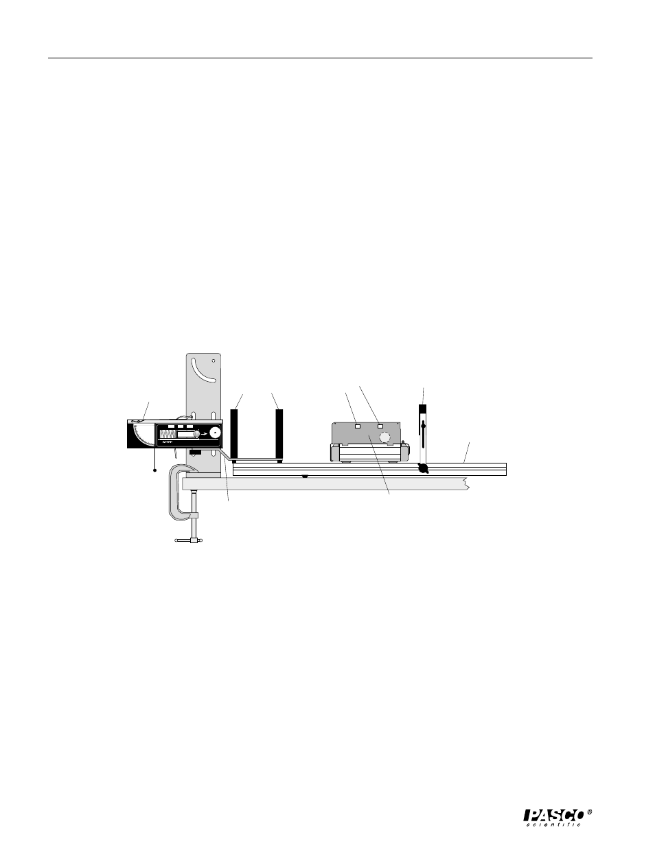
The initial speed (muzzle velocity) of the ball is determined using two photogates
mounted on the Launcher, and the final speed of the cart is found using a photogate
mounted on the track.
Setup
1. Clamp the Projectile Launcher to a sturdy table (near one end of the table with the muzzle
end facing inward toward the table).
2. Attach the photogate bracket to the Launcher, and attach two photogates to the bracket.
Plug the photogates into the computer photogate timing system (or the Four-to-One
Adapter). The photogate nearest the muzzle has to be plugged into port number one since
the ball will go through it first.
3. Place the dynamics track on the table with one end against the base of the launcher. Mount
the Projectile Launcher in the lower two slots on its base. Align the track with the launcher
by sighting through the launcher sites at the far end of the track. See Figure 2.2. The track
must be aligned with the launcher so the ball pushes the cart straight down the track
without derailing it.
4. Adjust the angle of the Projectile Launcher to zero degrees so the ball will be shot off
horizontally. Mount the catcher on the cart. Place the cart on the track at the end nearest
the Launcher with the opening of the catcher facing the Launcher. Adjust the height of the
Launcher so the ball will be shot into the center of the catcher.
5. Position a photogate on the track so the cart will block the beam immediately after the
collision with the ball. The initial position of the cart should be as close to the Launcher’s
photogate bracket as possible. Adjust the height of the photogate so the infrared beam will
pass through the slots in the side of the catcher.
6. Run the timing program, and set it to measure the gate and pulse time between three
photogates. If the Four-to-One Adaptor is being used, use Motion Timer.
CAUTION!
DO NOT LOOK
DOWN BARREL!
CAUTION!
DO NOT LOOK
DOWN BARREL!
CAUTION!
DO NOT LOOK
DOWN THE
BARREL.
LONG
RANGE
MEDIUM
RANGE
SHORT
RANGE
Position
of Ball
Launch
SHORT RANGE
PROJECTILE LAUNCHER
ME-6800
Yellow Band in Window
Indicates Range.
9
0
8
0
7
0
6
0
5
0
4
0
3
0
2
0
1
0
0
WEAR
SAFETY
GLASSES
WHEN IN USE.
Use 25 mm
balls ONLY!
Figure 2.2: Track Set-Up
launcher
dynamics track
Photogates
Photogate
attached to track
ball catcher
mounted on
Dynamics Cart
slots for
photogate
timing
Photogate Bracket