Assembly, Laser alignment, Set up projectile launcher as required – PASCO OS-8527A LASER SIGHT ACCESSORY User Manual
Page 2: Figure 2: laser alignment diagram, Figure 3: laser beam alignment, Figure 4: laser target fixture detail
2
Laser Sight Accessory
012-12247A
®
9 VD
C 50
0mA
GN
D
3.5mm
HOR
IZO
NTA
L
ADJ
UST
VER
TIC
AL
ADJ
UST
ON
OFF
POW
ER
+9V
DC
OS-8
527A
LASER SIGHT
ACCESSOR
Y
Manu
factu
red b
y:
10101 F
oothill Blvd.
Rose
ville, CA 95747 USA
®
➤
CAUTION: This is a relatively safe, low
power laser. Nevertheless, we strongly recom-
mend the following precautions:
• Never look directly into the laser beam, either
directly, or as it is reflected from a mirror.
• Set up experiments so the laser beam is NOT at
eye level (for spectators who may be either sit-
ting or standing).
Assembly
➀
Set up Projectile Launcher as required.
➁
Attach Laser Sight Accessory to rear of Projectile
Launcher with supplied thumbscrew and square nut.
See Figure 1. Face of laser diode unit must be flush
against rear of launcher barrel.
➤
NOTE: A greater range of inclination angle for
the launcher can be achieved by attaching the Laser
Sight Accessory to the lower channel of the Projec-
tile Launcher. This, in effect, rotates the Laser Sight
Accessory and changes the direction of the horizon-
tal and vertical adjustments as labeled in back of the
laser diode unit.
➂
Plug the 9VDC adapter phone plug into the back
of the laser and turn on the laser.
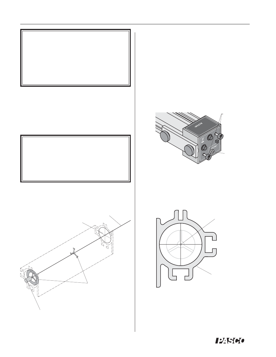
center of laser
target fixture
laser beam
bore-sights of
launcher
front of Projectile
Launcher barrel
laser module at
rear of launcher
laser target
fixture
Figure 2: Laser Alignment Diagram
Laser Alignment
It is necessary to align the laser beam so it passes pre-
cisely through the center of both bore-sights inside the
launcher barrel. See Figure 2.
Projectile Launcher must not be loaded during this proce-
dure.
➀
Cutout the supplied laser target fixture (see Figure
5) and place at the exit end of the Projectile
Launcher. Orientation is not critical.
➁
Use the horizontal and vertical adjustment screws
to adjust the direction of the laser beam from left-
to-right and up-and down until the beam is in
properly aligned. See Figure 3.
➂
Proper alignment is achieved when a single beam
is observed at the center of the face of the laser tar-
get fixture. See Figure 4.
Figure 3: Laser Beam Alignment
input jack
adjustment
screws
Figure 4: Laser Target Fixture Detail