PASCO CI-6685 BNC ADAPTER User Manual
Page 2
BNC Adapter
012-07157A
2
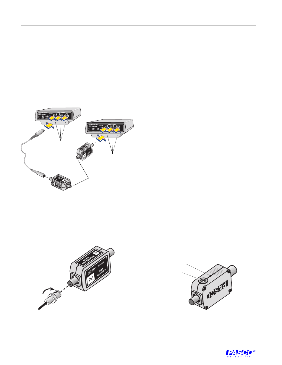
Setup Procedure
1.
Connect the BNC Adapter to any analog channel
on the ScienceWorkshop computer interface box
with the interface cable (Figure 1a),
or
Insert the DIN plug of the BNC Adapter into the
jack of any analog channel on the
ScienceWorkshop computer interface box (Figure
1b).
Figure 1
Connecting the BNC Adapter to the
Science-
Workshop computer interface
2. Connect the BNC connector of the probe to the
BNC Adapter as shown in Figure 2.
About the BNC Adapter
The BNC Adapter allows probes equipped with BNC
connectors (including those sold by Pomona
Electronics) to be used with ScienceWorkshop
interfaces.
The CI-6685 BNC Adapter adapts a probe with a male
BNC connector to a 5-pin DIN style input. The
adapter allows only single-ended measurements (i.e.,
measurements that are ground referenced).
Caution: Connecting a probe’s ground lead to any
potential other than ground could cause damage to the
circuit being measured, the BNC Adapter, or the
ScienceWorkshop Interface.
Mounting on an Experimental Apparatus
1. Use the 1/4–20 threaded screw connector located
on the bottom of the sensor box to secure the BNC
Adapter to an experimental apparatus (Figure 3).
The alignment hole fits over an alignment pin
included on some PASCO apparatuses.
Figure 3
Connections for mounting on some PASCO
experimental apparatuses
Figure 2
Connecting the user-supplied probe with a BNC
connector to the BNC Adapter
3.
Set up the BNC adapter in the data acquisition
software program (ScienceWorkshop or
DataStudio) as if it were a Voltage Sensor:
Associate the Voltage Sensor icon with the picture
of the analog channel that the BNC Adapter is
plugged into.
Plug into
any analog
channel.
Plug into
any analog
channel.
Connect user-
supplied probe.
1/4–20 threaded
screw connector
alignment hole