Experiment 3: tube length and resonant modes, Introduction, Procedure – PASCO WA-9612 RESONANCE TUBE User Manual
Page 17: Equipment needed, Figure 3.1 equipment setup, On off on off, Manual auto, Plunger, Piston function generator oscilloscope
012-03541E
Resonance Tube
13
Experiment 3: Tube Length and Resonant Modes
➤ WARNING: You can damage the speaker by overdriving it. The sound from the speaker
should be clearly audible, but not loud. Note also that many signal generators become
more efficient and thus produce a larger output as the frequency increases, so if you
increase the frequency, you may need to reduce the amplitude.
➁ Slowly push the piston further into the tube, until you hear the sound from the speaker
being amplified by the tube, indicating that you have produced a standing wave in the tube.
Adjust the piston position carefully until you find the point which produces the loudest
sound as well as the largest signal on the oscilloscope screen. Record this position.
➂ Now continue moving the piston into the tube until you reach a new position where a
standing wave is produced. Record this new position. Continue moving the piston until you
have found all of the piston positions along the tube which produce standing waves.
➃ Repeat the procedures above for as many different frequencies as your instructor directs.
EQUIPMENT NEEDED:
— PASCO Resonance Tube
— Function Generator
— Frequency Counter (if your function generator does not accurately indicate frequency)
— Oscilloscope (recommended, but not necessary)
Introduction
For any given tube length, there are a variety of resonant frequencies—frequencies at which
standing waves will be formed in the tube. Likewise, for a given frequency, there are a
variety of tube lengths at which a standing wave will be formed. In this experiment you will
examine the series of tube lengths which will resonate with a set frequency.
Procedure
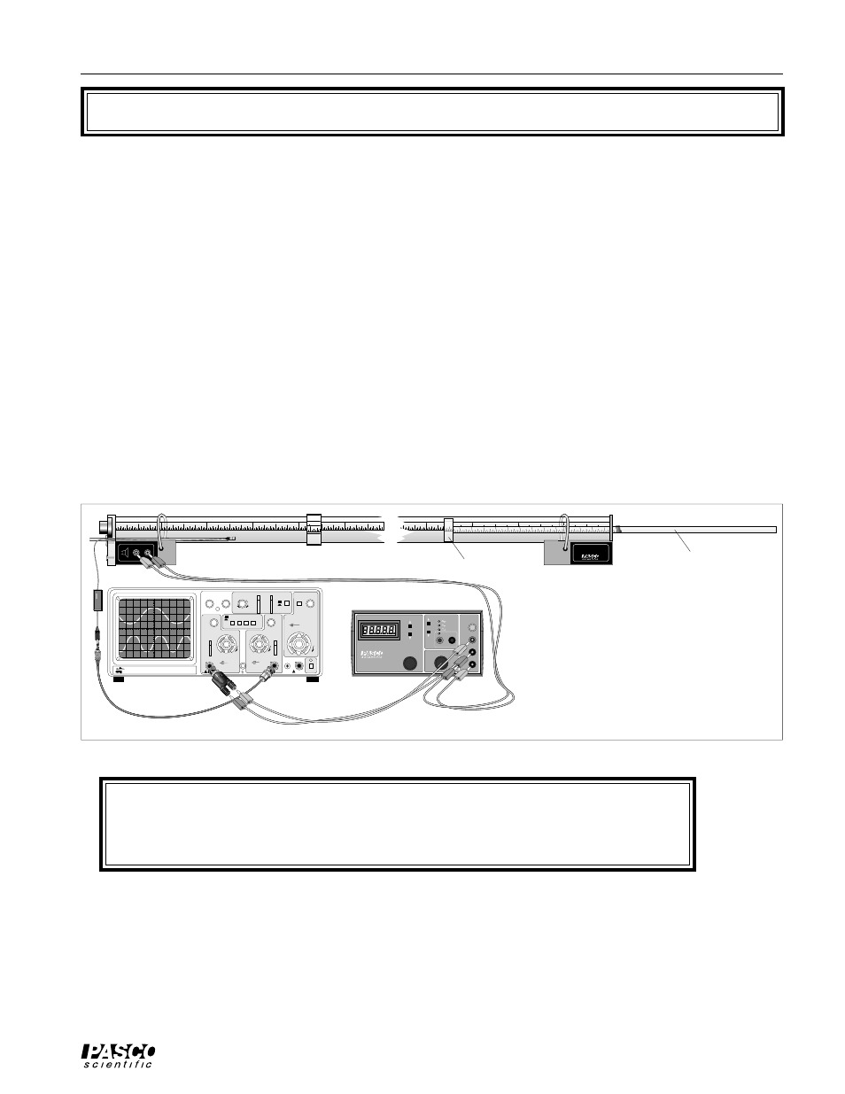
➀ Set up the Resonance Tube, oscilloscope, and function generator as shown in Figure 3.1.
Move the piston to a position very near the end of the tube. Set the signal generator to
approximately 800 Hz and turn the amplitude up until the speaker is clearly heard. Record
this frequency. If you use the oscilloscope, trigger on the speaker output.
1
2
3
4
5
SPEAKER INPUT
.1 W MAX
ON
OFF
ON
OFF
1
2
3
4
5
10
11
12
13
14
11
12
13
14
WA-9612
RESONANCE TUBE
13
13
BK PRECISION
200 Mhz OSCILLISCOPE
MODEL 2120
INTENSITY
FOCUS
TRACE NOTATION
TRIG LEVEL
COUPLE
SOURCE
SLOPE
λ
- Y
TIME/DIV
X-POS
VAR
VAR
VAR SWEEP
CAL
CAL
mV
V
CH 1 VOLTZ/DIV
CH 2 VOLTZ/DIV
CAL
mV
V
VERTICAL MODE
PULL XS
PULL XS
CH 2
∞
CH 1
∞
AC
DC
AC
DC
AC
CH1
CH2
ALT
EXT
POS
POS
NORM
EXT
CH1
CH2
NORM
EXT
CH1
CH2
MANUAL AUTO
T X-Y
T X-Y
LINE
CAL
EXT CH4
POWER
200V MAX
400V MAX
400V MAX
-
+
+
-
T T L
H I
Ω
G N D
L O
Ω
M I N
R A N G E
A D J U S T
M A X
O U T P U T
F R E Q U E N C Y
A M P L I T U D E
P I - 9 5 8 7 B
D I G I T
A L F U N C T I O N
G E N E R A
T O R - A M P L I F I E R
H E RT Z
W AV E F O R M
I N P U T
G N D
E X T E R N A L
Plunger
Figure 3.1 Equipment Setup
Piston
Function generator
Oscilloscope