Experiment 2: standing waves in a tube, Introduction, Procedure – PASCO WA-9612 RESONANCE TUBE User Manual
Page 13: Equipment needed, Figure 2.1 equipment setup, Manual auto, On off on off
012-03541E
Resonance Tube
9
Experiment 2: Standing Waves in a Tube
EQUIPMENT NEEDED:
— PASCO Resonance Tube
— Function Generator
—Frequency Counter (if your function generator does not accurately indicate frequency)
— Oscilloscope (recommended, but not necessary)
Introduction
A sound wave propagating down a tube is reflected back and forth from each end of the tube,
and all the waves, the original and the reflections, interfere with each other. If the length of the
tube and the wavelength of the sound wave are such that all of the waves that are moving in the
same direction are in phase with each other, a standing wave pattern is formed. This is known as
a resonance mode for the tube and the frequencies at which resonance occurs are called resonant
frequencies. In this experiment, you will set up standing waves inside the Resonance Tube and
use the miniature microphone to determine the characteristics of the standing waves.
Procedure
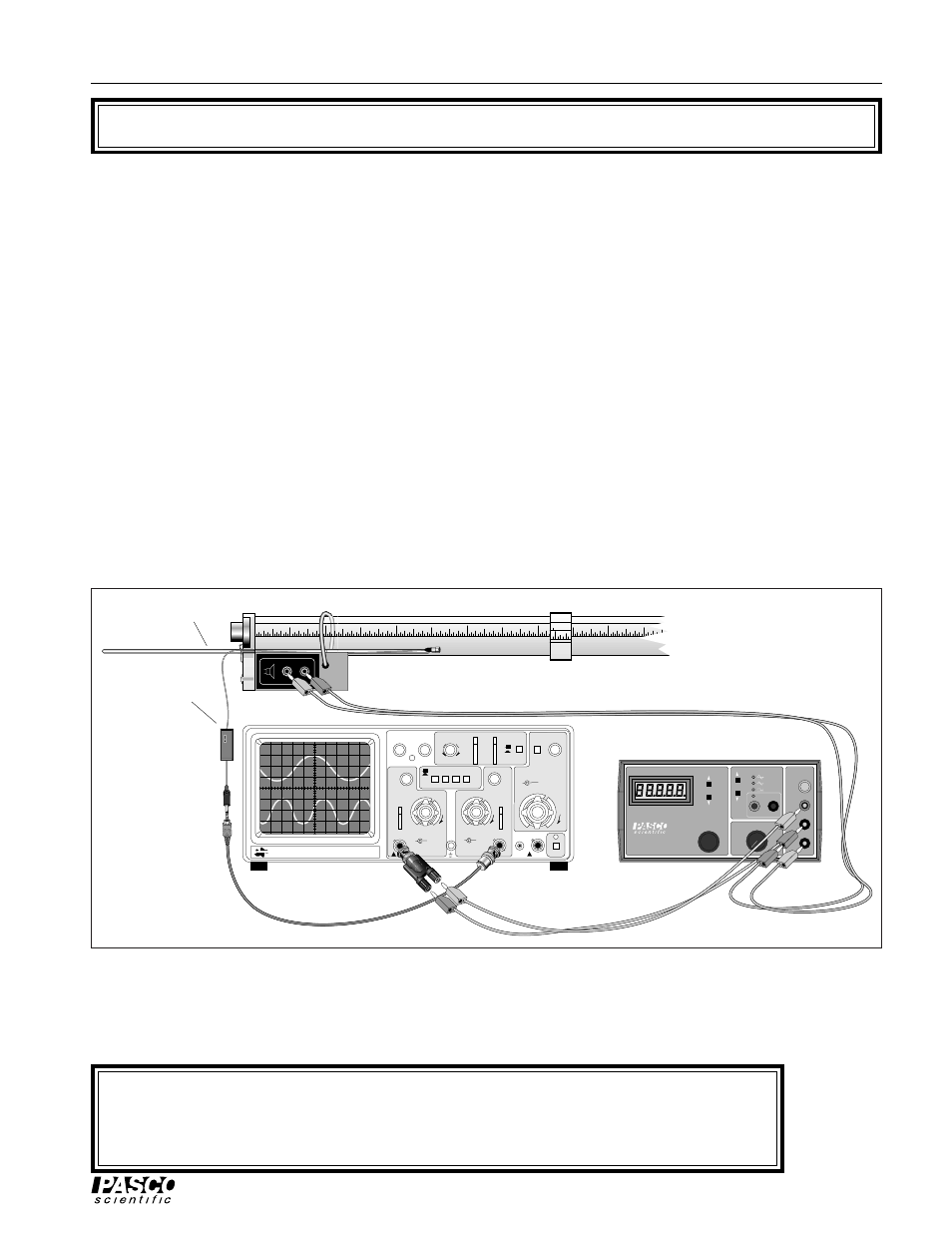
➀ Set up the Resonance Tube, oscilloscope, and function generator as shown in Figure 2.1. Turn on the
oscilloscope. Set the sweep speed to 5 ms/div and the gain on channel one to approximately 5 mV/div.
Figure 2.1 Equipment Setup
T T L
H I
Ω
G N D
L O
Ω
M I N
R A N G E
A D J U S T
M A X
O U T P U T
F R E Q U E N C Y
A M P L I T U D E
P I - 9 5 8 7 B
D I G I T
A L F U N C T I O N
G E N E R A
T O R - A M P L I F I E R
H E RT Z
W AV E F O R M
I N P U T
G N D
E X T E R N A L
BK PRECISION
200 Mhz OSCILLISCOPE
MODEL 2120
INTENSITY
FOCUS
TRACE NOTATION
TRIG LEVEL
COUPLE
SOURCE
SLOPE
λ
- Y
TIME/DIV
X-POS
VAR
VAR
VAR SWEEP
CAL
CAL
mV
V
CH 1 VOLTZ/DIV
CH 2 VOLTZ/DIV
CAL
mV
V
VERTICAL MODE
PULL XS
PULL XS
CH 2
∞
CH 1
∞
AC
DC
AC
DC
AC
CH1
CH2
ALT
EXT
POS
POS
NORM
EXT
CH1
CH2
NORM
EXT
CH1
CH2
MANUAL AUTO
T X-Y
T X-Y
LINE
CAL
EXT CH4
POWER
200V MAX
400V MAX
400V MAX
-
+
+
-
1
2
3
4
5
SPEAKER INPUT
.1 W MAX
1
2
3
4
5
ON
OFF
ON
OFF
Oscilloscope
Function generator
Microphone and
probe rod
Amplifier
Turn on the amplifier and the function generator. Set the output frequency of the function generator
to approximately 100 Hz. Adjust the amplitude of the function generator until you can distinctly
hear the sound from the speaker. If you use the oscilloscope, trigger on the speaker output.
➤ WARNING: You can damage the speaker by overdriving it. The sound from the speaker
should be clearly audible, but not loud. Note also that many signal generators become more
efficient and thus produce a larger output as the frequency increases, so you may need to
reduce the amplitude as you increase the frequency.