PASCO ME-6694 TORSION PENDULUM User Manual
Page 7
012–06339A
Torsion Pendulum
3
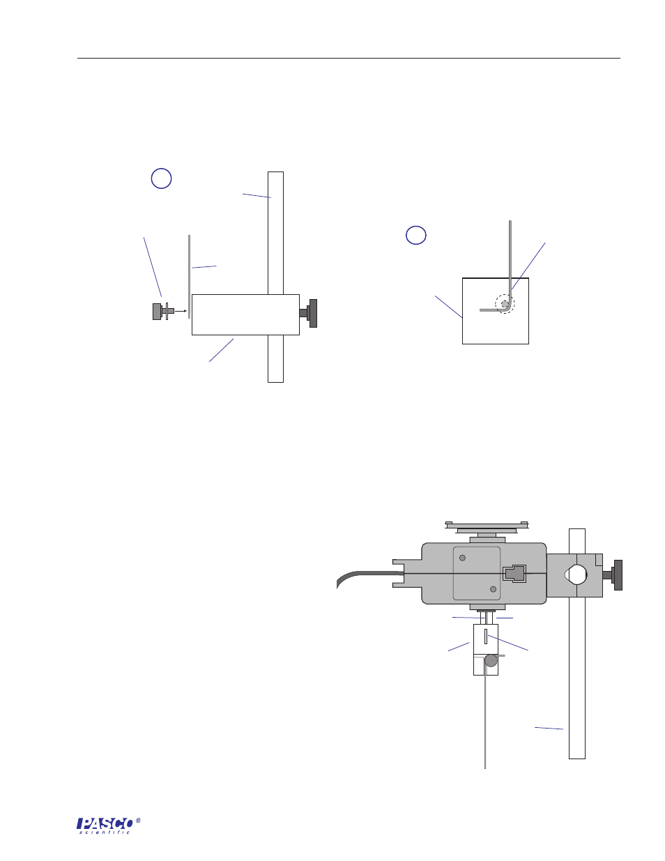
5.
Clamp the other end of the wire under the washer of the lower wire
clamp by tightening the thumbscrew firmly. Be sure that the
elbow of the bend in the wire fits snugly against the axle of the
thumbscrew (Figures 4a and 4b).
6.
Adjust the height of the lower wire clamp
to about 18 inches below the shaft of the
RMS.
7.
Align the guide of the upper wire clamp
with the slot of the shaft of the RMS. Slide
the upper wire clamp onto the shaft
(Figure 4).
8.
Adjust height of the lower wire clamp as
necessary to position to top of the upper
wire clamp approximately half-way up
the shaft (Figure 5).
9.
If necessary, adjust the lower wire clamp
so the wire is perpendicular to the table.
10.
Recheck all screws on the clamps to be
sure each part is firmly secured.
a
Support Rod
lower wire clamp
(side view)
wire
thumbscrew
and washer
wire
b
lower wire clamp
(front view)
thumbscrew
and washer
Figure 4
Lateral (a) and front (b) views of attaching the bent wire to the lower clamp.
slot
upper wire
clamp
guide
shaft of RMS
Support
Rod
Figure 5
Sliding the upper wire clamp onto the shaft of the Rotary
Motion Sensor
- UI-5000 850 Universal Interface Quick Start (1 page)
- UI-5000 850 Universal Interface Instruction Manual (24 pages)
- PS-2193 High Current Sensor (2 pages)
- ME-8979 Mass and Hanger Set (1 page)
- ME-9498A Photogate Head (3 pages)
- ME-6821A Photogate Mounting Bracket (2 pages)
- ME-6825A MINI LAUNCHER (39 pages)
- ME-6810 Time of Flight Accessory (24 pages)
- ME-8574 DISCOVER FRICTION ACCESSORY (4 pages)
- PS-2103A Motion Sensor (4 pages)
- PS-2189 High Resolution Force Sensor (2 pages)
- ME-9448B Super Pulley with Clamp (2 pages)
- ME-6955 1.2 m PAScar Dynamics System (27 pages)
- PS-2104 Force Sensor (2 pages)
- ME-8998 Elastic Bumper Kit (2 pages)
- ME-6843 Spring Cart Launcher (9 pages)
- ME-6950 PAScar with Mass (29 pages)
- PS-2120A Rotary Motion Sensor (9 pages)
- PS-2120A Rotary Motion Sensor (17 pages)
- ME-9821 Centripetal Force Pendulum (18 pages)
- ME-8088 Centripetal Force Apparatus (20 pages)
- ME-8735 Large Rod Stand (2 pages)
- CI-6545 Force Accessory Bracket (3 pages)
- ME-9806 Photogate Brackets (1 page)
- CI-6692 IDS MOUNT ACCESSORY (2 pages)
- ME-6569 RMS_IDS KIT (36 pages)
- ME-6829 Mini Launcher Ballistic Pendulum (18 pages)
- ME-9889 Discover Free Fall System (10 pages)
- SE-7256 Motion Sensor Guard (2 pages)
- ME-8973 Discover Collision Bracket (2 pages)
- AP-8214A Stress_Strain Apparatus (12 pages)
- CI-6691 MINI-ROTATIONAL ACCESSORY (2 pages)
- ME-9833 Physical Pendulum Set (30 pages)
- OS-8473 POLARIZER SET (2 pages)
- PS-2343 USB Camera (2 pages)
- AP-8215A Gravitational Torsion Balance (20 pages)
- OS-8526A X-Y ADJUSTABLE DIODE LASER (2 pages)
- Xplorer-GLX Users’ Guide (152 pages)
- PS-2150 Broad Spectrum Light Sensor (2 pages)
- PS-2164 Quad Pressure Sensor (3 pages)
- PS-2200 Load Cell, 100 N (3 pages)
- PS-2205 Dual Load Cell Amplifier (5 pages)
- PS-2107 Absolute Pressure Sensor (2 pages)
- PS-2102 pH Sensor (3 pages)
- PS-2119 Acceleration Sensor (2 pages)