PASCO OS-8533A POLARIZATION ANALYZER User Manual
Page 11
8
Polarization Analyzer
012-09200A
Consider the two extreme cases illustrated by this equation:
•
If Ø is zero, the second polarizer is aligned with the first polarizer, and the value of cos
2
Ø is one. Thus the
intensity transmitted by the second filter is equal to the light intensity that passes through the first filter. This
case will allow maximum intensity to pass through.
•
If Ø is 90º, the second polarizer is oriented perpendicular to the plane of polarization of the first filter, and the
cos
2
(90º) gives zero. Thus no light is transmitted through the second filter. This case will allow minimum inten-
sity to pass through.
•
These results assume that the only absorption of light is due to polarizer effects. In fact most polarizing films
are not clear and thus there is also some absorption of light due to the coloring of the Polaroid filters.
Procedure
In this activity, the Light Sensor measures the relative intensity of light that passes through two polarizers. You
will change the angle of the second polarizer relative to the first. The Rotary Motion Sensor measures the
angle.
The DataStudio records and displays the light intensity and the angle between the axes of the polarizers. You
can use the program’s built-in calculator to compare the relative intensity to the angle, the cosine of the angle,
and the cosine
2
of the angle.
Equipment Setup
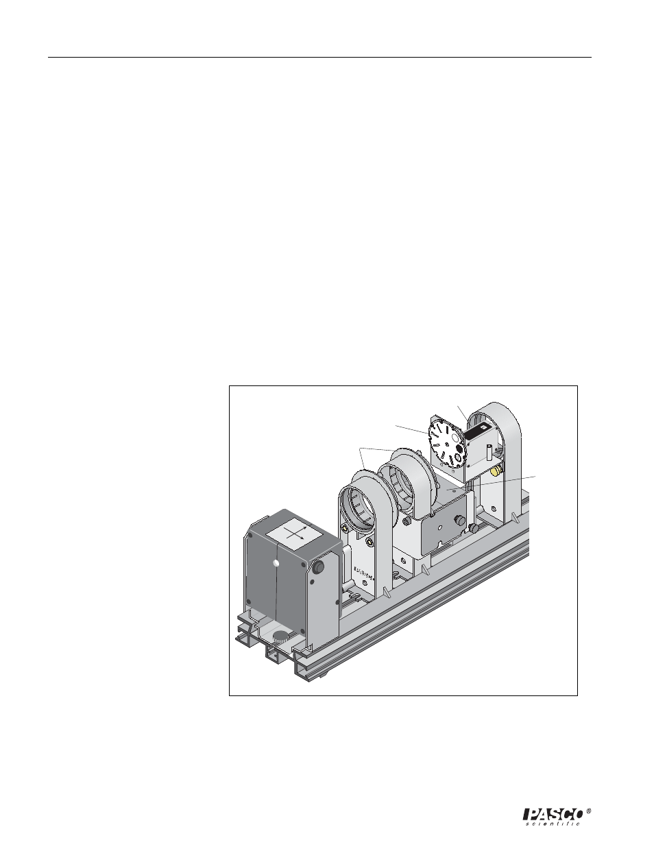
1. Mount the Basic Optics
Light Source, Polarizer
Holder, Polarizer Analyzer
with Rotary Motion Sensor,
and Aperture Bracket
Holder with Light Sensor as
shown. (Refer to the Intro-
duction for more informa-
tion.)
2. Connect the Light Sensor
and Rotary Motion Sensor
to the computer through a
ScienceWorkshop or
PASport interface (or inter-
faces), and start DataStudio.
PASCO
scientific
Light Sensor
Aperture Disk
Rotary Motion
Sensor
Polarizers
Light Source
Optics Bench
Figure 2: Equipment Setup