Introduction, Assembly, Usage – PASCO PS-2204 Displacement Sensor User Manual
Page 2
®
PASPORT Displacement Sensor
Introduction
2
Introduction
The PASPORT Displacement Sensor works with a Digital Indicator to measure dis-
placements to within 0.01 millimeters or 0.5 mils (thousandths of an inch) over a
range of 10.00 millimeters (0.3937 inches or 393.7 mils). The Displacement Sensor
comes with a Digital Indicator, a Pivot Rod Clamp for mounting the indicator on a
support rod (not included), and a screwdriver for removing or replacing the back
panel of the indicator.
The sensor cable from the Displacement Sensor connects to a small data port on the
left side of the indicator. The Displacement Sensor can be connected to any
PASPORT interface.
The Displacement Sensor is ideally suited to measure the small deflections of mem-
bers of a structure built using one of PASCO’s Structure Sets. For example, the sensor
can dynamically measure the deflection of the road bed of a bridge when a load is
applied to the structure.
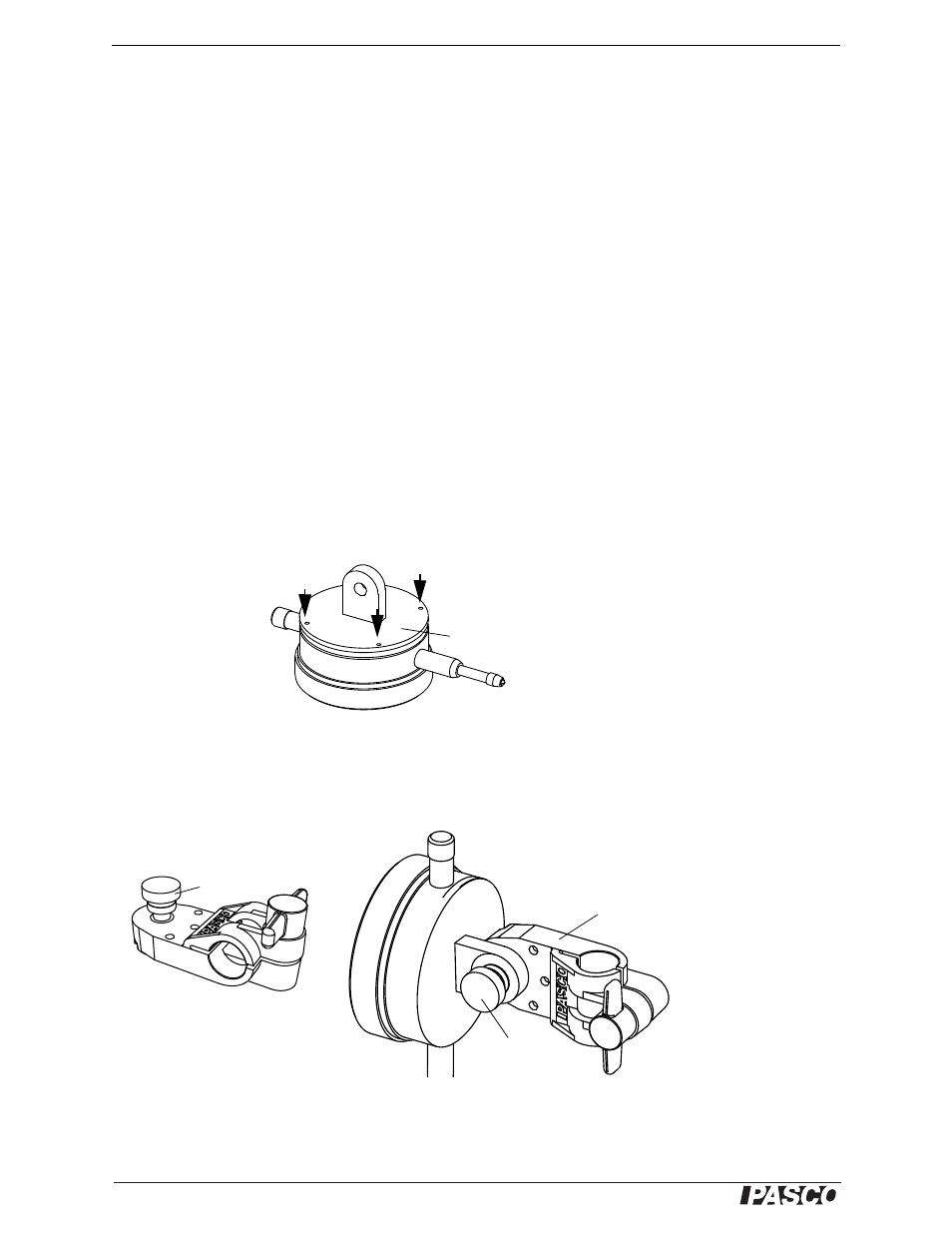
Assembly
The Digital Indicator can be mounted on a support rod up to 12 mm in diameter. To
mount the indicator on a support rod, first replace the flat back panel of the indicator
with the back plug panel found in the storage box. Use the small screwdriver from the
storage box to unscrew the flat back panel. (Be careful to keep the screws.) Align the
back plug panel with the back of the indicator and replace the four small screws.
Usage
Unscrew the round thumbscrew from the Pivot Rod Clamp. Align the hole in the back
plug panel on the indicator with the hole in the Pivot Rod Clamp and replace the
round thumbscrew. Mount the Pivot Rod Clamp on a support (12 mm diameter).
Back Plug Panel
Replace screws
Pivot Rod Clamp
Thumbscrew
Pivot Rod Clamp
Remove