Setup, Hardware setup, Datastudio setup – PASCO PS-2157 Temperature Array User Manual
Page 2
®
T e m p e r a t u r e A r r a y
Setu p
2
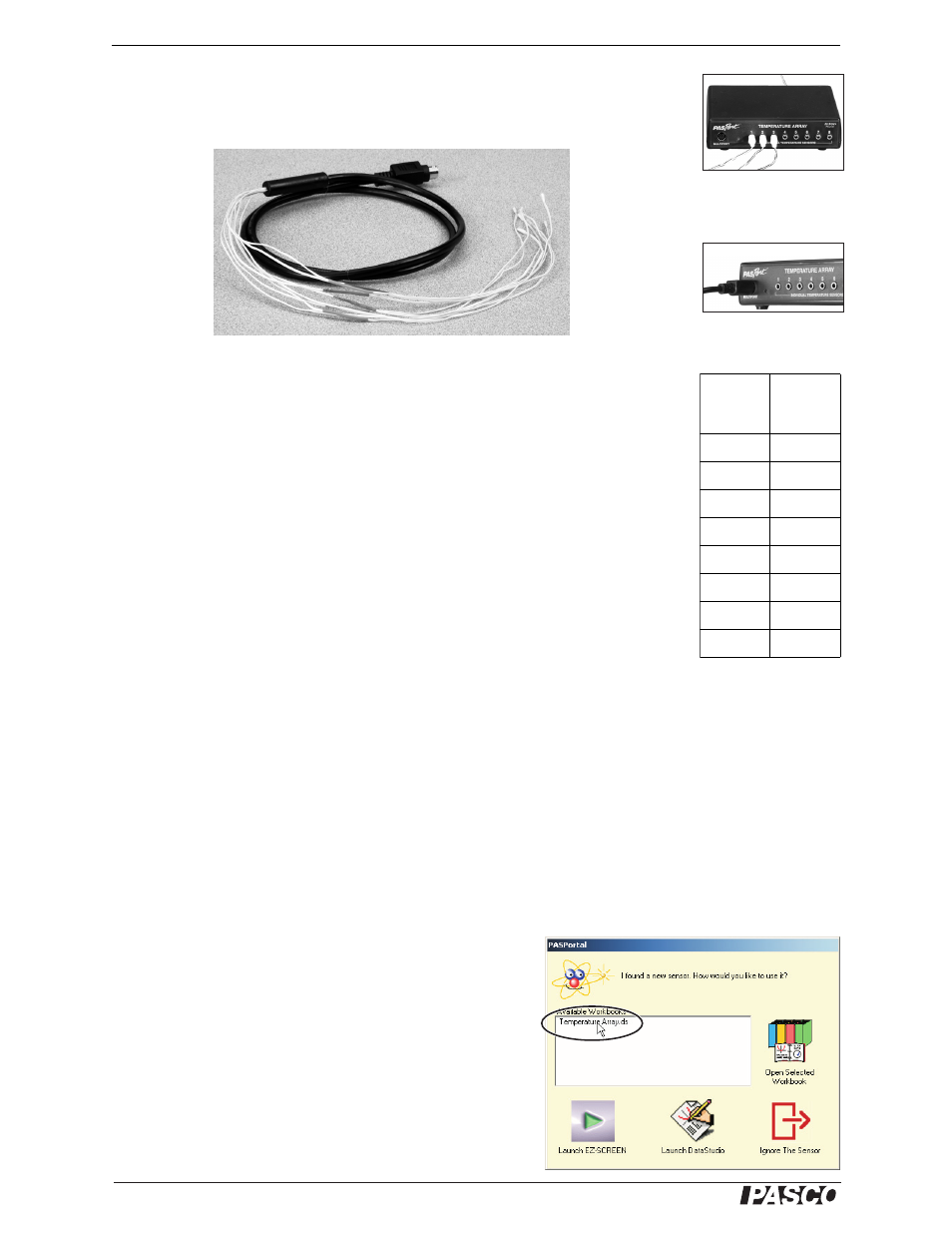
Separate temperature probes (such as the three included fast-response probes) can be
connected to the individual input ports, numbered 1 through 8 (right); or the special
eight-probe bundle (below) can be connected to the multiport (below right).
Eight-probe bundle
Each of the probes in the eight-probe bundle is identified by a colored band. The col-
ors correspond to the Temperature Array’s data channel numbers as shown in the
table (right).
When measuring the surface temperature of a person or object, use the included adhe-
sive patches to attach the probes.
Other PASCO devices containing embedded 10 k
Ω
thermistors (such as the Heat
Conduction Apparatus, TD-8513) can be connected to the individual ports or the mul-
tiport of the Temperature Array using the cables included with those devices.
Setup
Hardware Setup
The following three steps can be performed in any order.
1.
Connect the eight-probe bundle to the multiport or connect up to eight separate
temperature probes to the individual input ports.
Probes can be connected to the individual ports in any order (you don’t have to start with port 1),
and any of the ports can be left unconnected.
Do not use the individual ports and the multiport at the same time.
2.
Connect the cable of the Temperature Array to a PASPORT interface.
3.
If you will be using a computer, connect the PASPORT interface to the com-
puter’s USB port.
DataStudio Setup
If you will be using the Temperature Array with a computer, install
DataStudio version 1.9.5 first.
1.
When you connect the Temperature Array to the computer
through a PASPORT interface, the PASPortal window will
launch automatically (if DataStudio is not already run-
ning.
2.
Double click Temperature Array.ds to open the Tempera-
ture Array’s configured file in DataStudio.
Eight-probe bundle
connected to multiport
The color scheme is simi-
lar to the one commonly
used to identify resistor
values.
Color
Data
Channel
Number
Brown
1
Red
2
Orange
3
Yellow
4
Green
5
Blue
6
Violet
7
Gray
8
Three probes
connected to
individual ports
double click